
Operation Manual


Dimension BST 1200 / SST 1200 User Guide
Maintenance 57
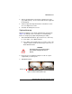
B. The printer will now begin to load material. See "Loading
Material", paragraphs 9 and 10 on page 35 for procedure
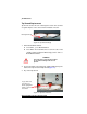
C. After Material Loading is complete the printer will display
Tip Calibration - Install Modeling Base And
Build Calibration Part.
D. Select Start Part (flashing).
Tip Calibration
Tip Replacement requires that a Tip Calibration must be
performed. When you select Start Part the printer will run two
calibration parts.
The printer will automatically build a Z Calibration part, measure
the part and calibrate the Z Axis for tip depth and tip level
(approximately 5 minutes).
The printer will then automatically build an XY Calibration part
(approximately 10 minutes). You must inspect the XY Calibration
part and calibrate the X and Y axes for tip offset:
1. When the XY Calibration part is complete the printer will
display Remove Part and Select XY Adjustment -
X:0, Y:0
2. Remove the XY tip calibration part from the Dimension printer.
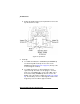
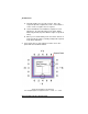
3. Inspect the part and calibrate the X and Y axes (See Figure 25
on page 58).
A. Use the magnifier from the Startup Kit to view the support
road (shown in red).
B. Identify the location on the +X or –X side of the part
where the support road is best centered within the model
boundaries (shown in blue).
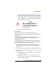
CAUTION
Make sure a NEW, UNUSED modeling
base is installed before starting
calibration. Calibration results will be
incorrect if a NEW, UNUSED modeling
base is not used.