
User Manual


Mode 1: Analog Input
Analog input mode is selected by setting switches 1 and 2 to the UP position. Switch 3 should be
either up or down, depending on the battery type being used. Inputs S1 and S2 are configured as
analog inputs. The output impedance of the signals fed into the inputs should be less than 10k
ohms for best results. If you are using a potentiometer to generate the input signals, a 1k, 5k or
10k linear taper pot is recommended. Remember to connect 0V to the ground of your control
circuit.
There are 6 operating options for analog input. These are selected with switches 4 and 5.
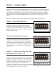
Option 1: Analog Bi-direction
A signal of 2.5 volts corresponds to the motor being
stopped. 0v corresponds to full power reverse, and 5v
corresponds to full power forward mode. This is useful for
direct bi-directional control of motors. There is one input,
which is connected to S1.
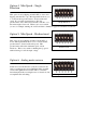
Option 2: Analog One-direction
A signal of 0v corresponds to the motor being fully
stopped. 5v corresponds to full power forward. The motor
acts single-direction only, and cannot be commanded to
reverse. This is useful for fans, pumps, propellers and other
single-direction only loads. There is one input, which is
connected to S1
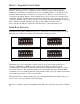
Option 3: Analog One-direction with
forward/reverse select on S2
A signal on S1 of 0v corresponds to the motor being fully
stopped. 5v corresponds to full power. A second signal is
fed to S2. If the signal on S2 is greater than 2.5 volts, the
SyRen will drive the motor forward. If the signal on S2 is
less than 2.5 volts, the SyRen will drive the motor
backwards. The signal on S2 can be either an analog signal
or a digital signal. This is useful for oscillating loads that go back and forth at a preset speed, as
well as vehicles with a reverse selector switch.
Analog Bi-direction mode
Analog One-direction mode
Analog One-direction mode with
forward/reverse select on S2