SyRen 10 / SyRen 25 motor driver user’s guide July 2007 Input voltage: 6-24V nominal, 30V absolute max. Output Current: Up to 10A/25A continuous. Peak loads may be up to 15A/45A for a few seconds. These ratings are for input voltages up to 18v in still air without additional heatsinking. For thermal, airflow and voltage rating charts for voltages over 18V see the back inside cover. Recommended power sources are: • • • • 5 to 18 cells NiMH or NiCd 2s to 6s lithium ion or lithium polymer.
Features Synchronous regenerative drive: Going one step farther than just regenerative braking, a SyRen motor driver will return power to the battery any time a deceleration or motor reversal is commanded. This can lead to dramatic improvements in run time for systems that stop or reverse often, like a placement robot or a vehicle driving on hilly terrain.
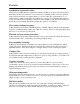
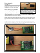
Hooking up the SyRen motor driver All connections to the SyRen are done with screw terminals. This makes it easy to set up and reconfigure your project. If you’ve never used screw terminal connections before, here is a quick overview.
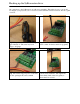
Motor Terminals M1 and M2 The motor is connected to terminals M1 and M2 as shown below. If the motor runs in the opposite way that you want, you may reverse the motor wires to reverse rotation. The motor connects to terminals M1 and M2 Signal Input Terminals S1 and S2 The input signals that control the SyRen are connected to terminals S1 and S2. S1 is the primary input, and must always be connected.
Power terminals 0V and 5V The 0V and 5V connections are used to power and interface to low-power control circuits. The 5V connection is a 5v power output. The 5V terminal can be used to power small This is useful for supplying power to lowloads, like a potentiometer or a radio receiver. current devices, such as a potentiometer or a The 0V signal must be connected to the ground radio receiver. The 5v terminal is capable of of the device generating the input signal.
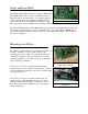
Status and Error LEDs The SyRen 10 and SyRen 25 have two indicator LEDs. The green LED marked status is used to communicate various information about the current state. Its operation depends on the operating mode. For example, if a lithium battery Status LED on pack is selected, the status LED blinks the number of cells detected. Unless you are in lithium mode, the status LED will usually remain off. The Error LED illuminates if the SyRen has detected a problem.
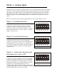
Operating Modes Overview Mode 1: Analog Input Analog input mode takes one or two analog inputs and uses those to set the speed and direction of the motor. The valid input range is 0v to 5v. This makes the SyRen easy to control using a potentiometer, the PWM output of a microcontroller (with an R-C filter) or an analog circuit. Major uses include joystick or foot-pedal controlled vehicles, speed and direction control for pumps and machines and analog feedback loops.
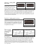
Lithium cutoff: Switch 3 of the DIP switch block selects lithium cutoff. If switch 3 is in the down position as shown the SyRen will automatically detect the number of series lithium cells at startup, and set a cutoff voltage of 3.0 volts per cell. The number of detected cells is flashed out on the Status LED. If the number of cells detected is too low, your battery is in Lithium Cutoff enabled a severely discharged state and must be charged before operation.
Mode 1: Analog Input Analog input mode is selected by setting switches 1 and 2 to the UP position. Switch 3 should be either up or down, depending on the battery type being used. Inputs S1 and S2 are configured as analog inputs. The output impedance of the signals fed into the inputs should be less than 10k ohms for best results. If you are using a potentiometer to generate the input signals, a 1k, 5k or 10k linear taper pot is recommended. Remember to connect 0V to the ground of your control circuit.
Option 4: Analog DiffDrive Mix Diff-Drive Mix is used for robots and vehicles with tank style steering using two SyRens. Two analog Analog Diff-Drive Right Analog Diff-Drive Left signals are fed into S1 and S2. The signal fed into S1 is the forwards/back command (0v full reverse, 5v full forward, 2.5v stop) and the signal fed into S2 is the turn command (0v turn right, 2.5v go straight, 5v turn left) These are mixed inside the controller to command right and left wheels.
Mode 2: R/C Input R/C input mode is used with a standard hobby Radio control transmitter and receiver, or a microcontroller using the same protocol. R/C mode is selected by setting switch 1 to the DOWN position and switch 2 to the UP position. If running from a receiver, it is necessary to obtain one or more servo pigtails and hook them up according to figure 5.1. If there are only motor drivers being used it is acceptable to power the receiver directly from a SyRen as shown.
Option 3: R/C DiffDrive Mix R/C Diff-Drive Mix is used for robots and vehicles with tank style steering using two SyRen motor drivers. Using this mode requires two R/C channels to be fed into S1 and S2 of both controllers. This can be accomplished with four servo pigtails and two Y-Cables, or two servo pigtails and some solder. The proper setup diagram is shown in Figure 5.3. The channel fed into S1 is used for forward/reverse control, and the channel fed into S2 is used for steering control.
A note on certain microprocessor receivers Some receivers, such as the Spektrum AR6000, will output servo pulses before a valid transmitter signal is present. This will cause the SyRen to autocalibrate to the receiver’s startup position which may not correspond to the center stick position, depending on trim settings. This may cause the motors to move slowly, even when the transmitter stick is centered.
Mode 3: Simplified Serial Mode Simplified serial uses TTL level single-byte serial commands to set the motor speed and direction. This makes it easy to interface to microcontrollers and PCs, without having to implement a packet-based communications protocol. Simplified serial is a one-direction only interface. The transmit line from the host is connected to S1. The host’s receive line is not connected to the SyRen. Because of this, multiple drivers can be connected to the same serial transmitter.
Option 1: Standard Simplified Serial Mode Serial data is sent to input S1. The baud rate is selected with switches 4 and 5. Commands are sent as single bytes. Sending a value of 0 will cause the motor to drive full forward, and sending a value of 255 will cause the motor to drive reverse. A value of 127 will cause the motor to stop.
Mode 4: Packetized Serial Mode Packetized Serial uses TTL level multi-byte serial commands to set the motor speed and direction. Packetized serial is a one-direction only interface. The transmit line from the host is connected to S1. The host’s receive line is not connected to the SyRen 10 or 20. Because of this, multiple SyRens can be connected to the same serial transmitter.
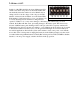
Address Byte Configuration: Address bytes are set by switches 4, 5 and 6. Addresses start at 128 and go to 135.
Commands: The command byte is the second byte of the packet. There are four possible commands in packetized serial mode. Each is followed by one byte of data 0: Drive forward (decimal 0, binary 0b00000000, hex 0h00) This is used to command the SyRen 10 and 20 to drive forward. Valid data is 0-127 for off to full forward drive. If a command of 0 is given, the SyRen will go into power save mode after approximately 4 seconds.
Checksum: To prevent data corruption, each packet is terminated with a checksum. If the checksum is not correct, the data packet will not be acted upon. The checksum is calculated as follows: Checksum = address byte +command byte +data byte The checksum should be added with all unsigned 8 bit integers, and then ANDed with the mask 0b01111111 in an 8 bit system. Example of Packetized Serial: The following is an example function for commanding a pair of SyRen 10s or 20s using Packetized Serial Mode.