
Data Sheet

www.dimensionengineering.com/products/Sabertooth2x32
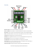
secondary functions of the S2 and A2 inputs. When in indicator mode, these pins have a built-in 220
ohm series resistor, so they can drive loads directly.
Power Outputs
These open collector outputs can sink up to 8 amps of
current each. The power outputs can be configured as
Voltage Clamps, Brakes or Controllable Outputs.
Voltage Clamp
With a typical regenerative driver, it is difficult to operate
from a power supply, because while braking there is
nowhere for the regenerated energy to dissipate. This can
lead to power supply shutdown or damage. By connecting
the power outputs to a resistor pack (sold separately, or
construct your own) the Sabertooth 2x32 can operate
from a power supply without an additional battery or
circuitry. The resistor’s value should be calculated to
provide the typical motor current or 8 amps, whichever is
less. Voltage clamp mode is selected using the Power
Outputs tab in the DEScribe
software. Voltage Clamp is the
default behavior for both the P1
and P2 outputs.
Brakes
The power outputs can also be
used to operate electromagnetic
brakes. Systems such as
wheelchairs often have brakes to
prevent rolling away when power
is removed. Brakes are also used in
CNC machines and automation to
hold alignment when power is
removed or reduce power
consumption. In brakes mode, the
brakes automatically disengage when motion is commanded, and engage when the motor stops. When
using Brakes mode, the P1 output is linked to the M1 motor output, and the P2 output is linked to the
M2 motor output. With the brake timing changed, brakes mode can also be used to control the field in a
shunt wound or separately excited motor. Brakes mode must be selected and configured from the
Power Outputs tab using the DEScribe software.
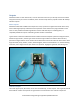
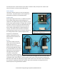
Power output connected to a resistor and
configured as a voltage clamp
Power outputs connected to electromagnetic brakes.