
Data Sheet

www.dimensionengineering.com/products/Sabertooth2x32
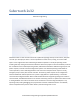
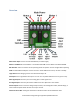
Overview
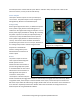
Main Power Input: Connect to a 6V-33.6V Battery or Power Supply.
Motor 1 and Motor 2: Connect Motor 1 to the M1A and M1B. Connect Motor 2 to M2A and M2B.
DIP Switches: These are used to set the operating mode and options. Can be changed while operating.
USB: A standard Micro USB port. Connect to a PC or other USB host to control, monitor or modify.
Logic Ground: The 0V logic ground is connected internally to B-.
5V Output: 5V is a regulated 5 volt output. You can use it to power additional circuitry up to 1 amp.
Main Signal Inputs: Connect your main analog, R/C or serial signals here.
Aux Signal Inputs: These may be used for additional control. Optional in most modes.
Power Outputs: These connect to voltage clamp resistors, electromagnetic brakes, field windings, or
other moderate power loads. 8A max current per channel.
Status and Error LEDs: These glow and flash to indicate the status of the Sabertooth 2x32.