
Data Sheet

www.dimensionengineering.com/products/Sabertooth2x32
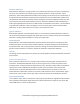
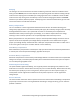
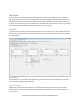
Power Outputs tab
The power outputs tab controls the behavior of the power outputs P1 and P2.
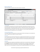
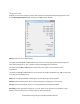
Mode
The power outputs must be put in the correct mode in order to have the expected function.
Voltage Clamp
In this mode, the power output P1 or P2 will turn on if the input voltage rises. This rise is due to
regenerated energy being fed back into a power supply that is not able to accept it. Connecting a power
resistor between the power output and the positive supply voltage and using this mode allows for
operation from a power supply. Max Voltage is the voltage above which the output will turn on.
Automatic compares the present input voltage to the average input voltage, and works well in most
cases. Moving the slider allows for a custom turn-on voltage.
Brakes
In this mode, the power outputs are used to operate electromagnetic brakes. P1 corresponds to motor 1
and P2 corresponds to motor 2. When the motor stops, the brakes activate after the Turn-On Delay.
When the motor is commanded to move again, the brakes deactivate immediately, but the motor does
not turn until the Turn-Off Delay has elapsed. If an emergency stop is commanded, the brakes will
activate after the E-Stop delay has elapsed.
Brakes mode can also be used to drive the field of a shunt or compound wound motor. To do this,
connect one side of the field to B+ and the other side of the field to the P1 or P2 power output. Turn all
the timings to 0 seconds.