
Data Sheet
www.dimensionengineering.com/products/Sabertooth2x32
Wiring
Power connections
As a general rule of thumb, you should use the thickest wire that is practical to make power
connections, especially on the battery leads. Using undersized wire will lead to the wire getting hot, and
can lead to elevated temperatures on the Sabertooth 2x32 as well.
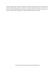
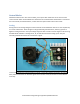
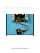
The main power connections to the Sabertooth 2x32 are on the rear edge of the board. Connections are
made to large black screw terminals. These terminals will accept 10 to 24 gauge wire. Using stranded
wire it is possible to run twinned 10 gauge wire connections to the battery terminals. This is often a
good idea if your design will be running both motors near or above the 32 amp continuous limit. For the
motor connections, single 10 gauge wires should be sufficient for all applications.
Motor 1 connects to the M1A and M1B terminals. Motor 2 connects to the M2A and M2B terminals.
If you are using the power outputs as regenerative clamps, one side of the resistor pack connects to the
P1 terminal, and the other side connects to the B+ terminal. You may find it easier to connect the
positive side of the power input through a bus bar or in the wiring harness instead of at the Sabertooth
itself. This is acceptable. By default the power outputs are set up for regenerative clamp.
If you are using the power outputs for electromagnetic brakes, the positive side of both brakes connect
to the B+ terminal. The negative side of the M1 brake connects to P1, and the negative side of the M2
brake connects to P2. Remember that to use brakes you must set the power outputs to brakes mode
using the DEScribe PC software.
If you are using the power outputs at a voltage other than the main system voltage, such as to run a 5v
cooling fan, connect the negative side of the device being powered to the P1 or P2 auxiliary power
output, and the positive side to that supply voltage. If you are using an inductive load such as a motor
from a different voltage, you will need to install a flyback diode across the device to prevent problems.
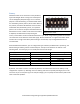
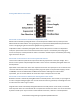
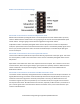
Signal connections
The signal connections, as well as the auxiliary power outputs, connect to the smaller green screw
terminals on the front edge of the board. All the signal inputs can accept signals between 0V and 5V. In
digital input modes, logic high can be between 2.7V and 5V. This allows for interface to boards using 3.3
or 2.7 volt microcontrollers without the need for level translators.
USB: The USB port is used for connection to a PC, tablet or advanced microcontroller. If only the USB
port is connected, the internal logic circuitry of the Sabertooth will be active, but neither input nor
output terminals will operate. This is useful to enable changing the operating options or updating the
firmware without powering on the entire device. In a production setting, it is also useful to set up the
Sabertooth 2x32 before installation.