
Data Sheet


www.dimensionengineering.com/products/Sabertooth2x32
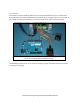
The R/C signal connected to S2 controls whether the motor driver responds to the serial input or the R/C
inputs. This is connected to channel 5 on the transmitter, which is a two position switch. In one position,
the Sabertooth will respond to the serial commands, in the other it will respond to the R/C signals.
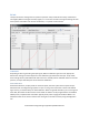
A1 and A2 are set up as R/C inputs with automatic calibration and differential drive mixing.
A1 is the forward/back input and is connected to the elevator channel of the transmitter.
A2 is the right/left input and is connected to the aileron channel of the transmitter.
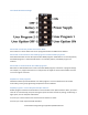
Default program 2: Analog with remote Indicator LEDs and current display
Default program 2 would be used when it is necessary to have the error indicator on a control panel.
Often when building machinery the Sabertooth 2x32 is tucked deep inside a control cabinet, so the
onboard LEDs are not visible. Also, for some applications it is useful to display the load current, to
prevent loading a mechanism. The power outputs P1 and P2 are used to drive analog panel meters to
display load current on each motor.
In this example, the M1 motor is set up bi-direction, with a potentiometer connected to S1 controlling
speed and direction.
The M2 motor is set up for separate speed and direction controls. A potentiometer going to A1 controls
the output speed, and a switch going between the 5V output and A2 controls the direction.
S2 is set to Indicator output and mirrors the error LED. If the error LED illuminates, an LED connected
between S2 and 0V will also illuminate.
P1 is connected with a 1k pull-up resistor to the 5V output and set as a controllable output, driven by
the internal M1 current reading. A 32 amp current reading will drive a full scale 5 volt output. Connect a
5V analog meter between P1 and 0V.
P2 is connected with a 1k pull-up resistor to the 5V output and set as a controllable output, driven by
the internal M2 current reading. A 32 amp current reading will drive a full scale 5 volt output. Connect a
5V analog meter between P2 and 0V.
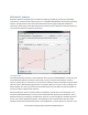
In addition to the example programs, User Mode equivalents for the other operating modes can also be
found in the Examples folder.