
Data Sheet

www.dimensionengineering.com/products/Sabertooth2x32
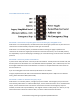
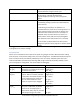
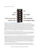
Serial Mode DIP Switch Settings
DIP Switch 4 selects between packet/plain text serial and legacy simplified serial.
If DIP switch 4 is in the ON position, the Sabertooth 2x32 is listening for packet serial or plain text serial
commands. It will automatically respond to either type of command.
If DIP switch 4 is in the OFF position, the Sabertooth 2x32 is listening for legacy simplified serial
commands. This mode uses single-byte commands to command each motor, and is included primarily
for compatibility. If you are developing a new design, we recommend using one of the newer command
protocols.
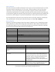
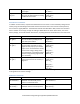
DIP Switch 5 selects the packet serial address.
In packet serial mode, DIP switch 5 sets the packet serial address. The ON position sets address 128, and
the OFF position sets the address to a user-definable alternate. By default, this is address 129, but it can
be changed in DEScribe. Packet serial addresses are used to run multiple Sabertooth motor drivers on
the same serial line.
If you are sending plain text serial commands, DIP switch 5 has no effect.
In legacy simplified serial, DIP switch 5 selects between 9600 baud (switch 5 ON) and a user-defined
setting, which defaults to 2400 (switch 5 OFF)
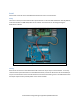
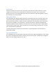
DIP Switch 6 enables or disables emergency stops.
If DIP switch 6 is in the OFF position, emergency stops are enabled. This emergency stop is active low
and internally pulled down. To enable the M1 output, connect the A1 terminal to 5V. To enable the M2
output, connect the A2 terminal to 5V. If these connections are broken and emergency stops are
enabled, the motors will stop immediately. This might be used for a safety E-stop in a machine, to only
allow motion while a dead-man switch is held, or to detect a disconnected control cable.