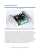
Sabertooth 2x32 Dimension Engineering Sabertooth 2x32 is a dual channel motor driver capable of supplying 32 amps to two motors, with peak currents up to 64 amps per motor. It can be operated from radio control, analog, TTL serial or USB inputs. It uses regenerative drive and braking for efficient operation. A variety of operating modes including tank style mixing and automatic calibration allow most projects to work immediately out of the box.
Contents Features ........................................................................................................................................................ 4 Overview ....................................................................................................................................................... 5 Specifications ................................................................................................................................................ 6 Inputs .......
Tools menu.............................................................................................................................................. 49 User Mode .................................................................................................................................................. 50 Setup tab ................................................................................................................................................. 50 Programs ............................
Features Dual motor driver with mixed and independent options Sabertooth 2x32 will drive two motors at up to 32A continuous and 64A peak each. These can be mixed together for a tank drive type vehicle, or run independently. It can be controlled by analog voltages, R/C transmitters, TTL serial commands, USB, or a combination of these signals. USB input Every third generation Sabertooth motor driver comes with USB standard.
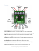
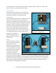
Overview Main Power Input: Connect to a 6V-33.6V Battery or Power Supply. Motor 1 and Motor 2: Connect Motor 1 to the M1A and M1B. Connect Motor 2 to M2A and M2B. DIP Switches: These are used to set the operating mode and options. Can be changed while operating. USB: A standard Micro USB port. Connect to a PC or other USB host to control, monitor or modify. Logic Ground: The 0V logic ground is connected internally to B-. 5V Output: 5V is a regulated 5 volt output.
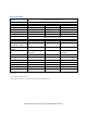
Specifications Dimensions Weight Wire size, battery Wire size, motors Wire size, signal Operating temperature Input voltage, B+ and BContinuous output current, M1 and M2 Peak output current, M1 and M2 Output voltage, M1 and M2 Voltage, P1 and P2 Output current, P1 and P2 Output voltage, 5V Output Current, 5V Input voltage, S1 and S2 Input voltage, A1 and A2 Output Voltage, S2 and A2 Mechanical specifications 2.75 x 3.5 x 1.0 inches (70mm x 90mm x 26mm) 4.
Inputs Main Signal Inputs The main inputs are labeled S1 and S2. They can be set for analog, R/C or serial communications. When using serial, S1 is the RX port and S2 is the TX port. Main signal inputs are labeled S1 and S2 Auxiliary Inputs The auxiliary inputs are labeled A1 and A2.They can be set for analog, R/C or serial communications. When using serial, A1 is the RX port and A2 is the TX port.
Outputs Sabertooth 2x32 is a dual motor driver, and can drive two motors at up to 32 amps continuous and 64 amps peak current per channel. In addition, there are two 8 amp auxiliary outputs and two 20 milliamp indicator outputs. Motor Outputs Sabertooth 2x32’s M1 and M2 motor outputs are 12 bit, synchronous regenerative motor drives. They have a switching frequency of 30 kHz for silent operation. Each channel has a programmable current limit.
secondary functions of the S2 and A2 inputs. When in indicator mode, these pins have a built-in 220 ohm series resistor, so they can drive loads directly. Power Outputs These open collector outputs can sink up to 8 amps of current each. The power outputs can be configured as Voltage Clamps, Brakes or Controllable Outputs. Voltage Clamp With a typical regenerative driver, it is difficult to operate from a power supply, because while braking there is nowhere for the regenerated energy to dissipate.
Controllable Output Finally, the power outputs can be used as additional variable power outputs. These could be used to drive fans, solenoids, valves, heaters or similar medium power devices. This is primarily used with serial or USB inputs, or custom User Mode programs. Controllable Output must be selected in DEScribe. www.dimensionengineering.
Input Power Sabertooth 2x32 can be used with power supplies or batteries. Input power is connected to the center power terminals labeled B+ and B-. The input voltage range of the Sabertooth 2x32 is 6.0V to 33.6V. The input current is dependent on the motors being used and the load placed upon them. The input current can be limited by reducing the current limit of one of both motor channels.
dissipate the regenerative current generated when the device slows down or stops. This allows the use of power supplies without batteries or capacitors to absorb the regenerated energy. A calculator on the Dimension Engineering website will assist with choosing appropriate resistor packs. At least one of the power outputs should be configured as a voltage clamp when using a power supply. www.dimensionengineering.
Battery Sabertooth 2x32 can be used with a variety of battery types and voltages. When running from a battery that can be damaged by deep discharge, such as a lithium polymer or lead acid battery, you should set DIP switch 3 to the battery protect position, which is OFF. When in this position, the Status LED will blink out the number of detected cells, followed by a pause, in a repeated pattern. This is useful to verify that the Sabertooth has detected the correct number of cells.
Wiring Power connections As a general rule of thumb, you should use the thickest wire that is practical to make power connections, especially on the battery leads. Using undersized wire will lead to the wire getting hot, and can lead to elevated temperatures on the Sabertooth 2x32 as well. The main power connections to the Sabertooth 2x32 are on the rear edge of the board. Connections are made to large black screw terminals. These terminals will accept 10 to 24 gauge wire.
0V: This is the main logic ground of the Sabertooth 2x32. It is internally connected to B-. 5V: This is a 5V output, and can supply up to 1A of current to devices such as receivers, potentiometers, microcontrollers or servos. S1: This is a main signal input. Its functionality depends on the operating mode. Input voltages into S1 should be between 0V and 5V. S2: This is a main signal input. Its functionality depends on the operating mode. Input voltages into S2 should be between 0V and 5V.
Control Modes Sabertooth 2x32 has four main control modes, plus a special User mode that can be used to create custom control modes. Control Modes are selected via the six DIP switches. DIP switches 1 and 2 select the control mode, and DIP switches 4, 5 and 6 select the options within each control mode. Analog Analog control uses analog voltages to send commands to the Sabertooth 2x32. This is the simplest way to control a Sabertooth.
Analog Mode DIP Switch Settings DIP switch 4 selects between mixed and independent mode. Mixed mode is selected by setting DIP switch 4 to the ON position. Mixed mode is primarily used for differential drive mobile vehicles. The signal going to S1 controls the forward/backwards speed of both motors. The signal going to S2 controls the right/left turning of both motors. Independent mode is selected by setting DIP switch 4 to the OFF position as shown.
switch for the signal being fed into S1. If only a single direction is needed, only S1 and S2 need to be connected. Speed ramping In all analog modes except Single Direction, an analog signal sent to the A1 auxiliary input controls the ramp rate for both channels of the motor driver. This is useful to make gentle motions or limit peak currents due to acceleration.
Radio Control Radio Control uses R/C (servo) pulses to send commands to the Sabertooth 2x32. These signals are generated by R/C transmitters and receivers, or by microcontrollers. Anything that can generate servo signals can be used to drive a Sabertooth in Radio Control mode. In Radio Control mode the S1, S2, and A2 inputs are set up to read R/C pulses. The A1 input is set up as an analog input and can be used with a potentiometer for an adjustable ramp rate.
Radio Control Mode DIP Switch Settings DIP switch 4 selects between mixed and independent mode. Mixed mode is selected by setting DIP switch 4 to the ON position as shown. Mixed mode is primarily used for differential drive mobile robots. The signal going to S1 controls the forward/backwards speed of both motors. The signal going to S2 controls the right/left turning of both motors. Independent mode is selected by setting DIP switch 4 to the OFF position as shown.
Microcontroller mode is selected by turning DIP switch 6 OFF. In microcontroller mode, the input pulse ranges are fixed. A 1500us signal is stopped, 1000us is full reverse and 2000us is full forward. To allow for slower microcontrollers like Basic Stamps, by default there is no timeout in Microcontroller mode. DEScribe can be used to override these settings and use other input ranges, as well as change the timeout behavior and timing.
Serial Serial mode is used to control the Sabertooth 2x32 from a PC or microcontroller. Setup There are a variety of serial communication protocols that can be used with Sabertooth 2x32. By default, all of these modes use 9600 baud, 8N1 TTL serial levels. The baud rate can be changed using the DEScribe PC software. A Sabertooth 2x32 receiving serial commands from an Arduino microcontroller Wiring Wire the S1 connection on the Sabertooth 2x32 to the serial TX pin of your microcontroller.
Serial Mode DIP Switch Settings DIP Switch 4 selects between packet/plain text serial and legacy simplified serial. If DIP switch 4 is in the ON position, the Sabertooth 2x32 is listening for packet serial or plain text serial commands. It will automatically respond to either type of command. If DIP switch 4 is in the OFF position, the Sabertooth 2x32 is listening for legacy simplified serial commands. This mode uses single-byte commands to command each motor, and is included primarily for compatibility.
Plain Text Serial Plain text serial mode uses ASCII formatted plain text strings to control the Sabertooth 2x32. This makes serial communications especially easy, as one can open a terminal window on a PC and start typing commands, or use a printf command on a microcontroller. Using Plain Text Serial mode allows full control of the Sabertooth 2x32. The tradeoff is plain text takes more data to send the same information, so the maximum update rate may be less.
R2: 2047\r\n Q1: 1\r\n Otherwise they will perform their normal voltage clamp or brake behavior and ignore serial input. This sets the speed ramping to the maximum amount. At this setting, it will take the Sabertooth approximately 8 seconds to go from a stop to full speed. By default the Q parameters control motor freewheeling. Setting a positive value will disable the motor channel. Freewheeling and shutdown are different.
A1: get\r\n A2: get\r\n program, they can be set to any of the input types. Returns the input value for the S1 or S2 inputs. By default these are analog in USB and serial modes. might return S2: 2012\r\n A1: get\r\n might return S1: -2047\r\n Extended Get commands In addition to these values, outputs of the Sabertooth such as motor current and battery voltage can be read by using the extended get commands. Because each motor has its own current and temperature, the structure is slightly different.
Packet Serial Packet serial mode uses much the same commands as plain text serial mode, but does so in a more compact binary communication protocol with a reliable checksum or CRC. There are open source libraries for Arduino and C# and sample code for both on the Dimension Engineering website, as well as documentation on the protocol itself.
USB Mode USB mode takes primary input from the USB port, using the same commands as the serial modes. USB mode can also use the Sabertooth 2x32 as a USB to serial converter, to relay commands from the PC to other serial devices, such as another Sabertooth motor driver or a Kangaroo x2 motion control card. A Sabertooth 2x32 connected to a USB cable Connect a USB Micro B cable to the USB port on the Sabertooth 2x32. Connect the USB cable to a PC, tablet or single board computer.
USB Mode DIP Switch Settings DIP switch 4 in the ON position selects USB mode. USB control uses the same commands as the serial modes. A Sabertooth 2x32 will appear to the operating system both as a serial port and as an HID device. Usually, the serial port is how you will send and receive commands from the Sabertooth. Dimension Engineering supplies an open-source C# library, as well as example code for other programming languages and platforms.
terminal of the Sabertooth 2x32 to the S1 terminal of the additional SyRen or Sabertooth drivers. Connect the A1 terminal to the S2 terminals to enable reading back data, if the device supports it. DIP Switch 6 enables or disables emergency stops. If DIP switch 6 is in the OFF position, emergency stops are enabled. This emergency stop is active low and internally pulled down. To enable the M1 output, connect the A1 terminal to 5V. To enable the M2 output, connect the A2 terminal to 5V.
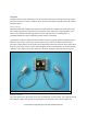
User Mode User modes are custom operating modes that are created inside DEScribe. They can combine input types and functions to create a Sabertooth tailored specifically for an application. This can cut down on the number of components needed for a product and enable more sophisticated functionality. A Sabertooth 2x32 connected to a serial input and a radio receiver, with a switch to select the controlling device and USB monitoring. In User Mode any of the inputs can be set as any of the input types.
User Mode DIP Switch Settings DIP switch 4 in the OFF position selects User Mode. User modes are custom modes that can be reprogrammed with the DEScribe PC software. DIP switch 5 selects between User Mode program 1 and User Mode program 2. Each Sabertooth 2x32 can have two separate User Mode programs. If DIP switch 5 is in the ON position, User Mode program 1 is selected. If DIP switch 5 is in the OFF position, User Mode program 2 is selected. DIP switch 6 is used inside the User Mode programs.
The R/C signal connected to S2 controls whether the motor driver responds to the serial input or the R/C inputs. This is connected to channel 5 on the transmitter, which is a two position switch. In one position, the Sabertooth will respond to the serial commands, in the other it will respond to the R/C signals. A1 and A2 are set up as R/C inputs with automatic calibration and differential drive mixing. A1 is the forward/back input and is connected to the elevator channel of the transmitter.
DEScribe PC software DEScribe is Dimension Engineering’s PC software for adjusting, modifying, monitoring and updating motor drivers, as well as certain other products. It is compatible with Windows XP and newer operating systems. Third generation motor drivers like Sabertooth 2x32 are highly configurable. DEScribe is necessary to access many of the advanced features of these products. DEScribe is a free download, and can be found on Dimension Engineering’s website.
OK. DEScribe will download the current settings. Any time you want to save the modified settings to the Sabertooth, click the Upload Settings to Device button. www.dimensionengineering.
General tab The General tab contains settings that affect the Sabertooth 2x32 in all modes and for all outputs. Startup Delay Startup Delay sets how long the Sabertooth 2x32 waits after power is applied to begin operation. This delay is to allow host microcontrollers to boot, receivers to start and analog voltages to stabilize. Min Voltage and Max Voltage Min Voltage and Max Voltage set the input voltages within which the Sabertooth 2x32 will operate normally.
Battery Battery selects the type of battery used and the number of cells. It is also possible to change the low voltage cutoff settings here. These settings go into effect when DIP switch 3 is in the OFF position. See the Battery section for more details. Exponential-Mode Mappings Sabertooth 2x32 can have up to four maps which modify the ratio of input signal to output signal.
Analog tab The Analog tab contains settings that are specific to operation in Analog mode. Each of the four analog inputs has the same options. Also, if in a different mode a pin is set for analog input, it is configured here. Calibration Depending on what is generating the input signal, different calibration types are most appropriate. Which other settings are active depends on the calibration type selected for the input.
delay (the Calibration Delay setting) the Sabertooth will take whatever voltage level is presented at the input and use that as its zero speed setting. It will then constantly look for the largest and smallest voltage that it has ever seen, and use these values as full speed forward and reverse. Automatic calibration is very helpful for signals such as low-cost joysticks that have significant variability in their center and end values.
RC tab The R/C tab contains settings that are specific to operation in R/C mode. Because every manufacturer uses slightly different timing for their R/C signals, it is not unusual to have to change the settings to work with a specific transmitter and receiver combination, or a specific microcontroller. Calibration Depending on what is generating the input signal, different calibration types are most appropriate. Which other settings are active depends on the calibration type selected for the input.
Automatic Calibration With Automatic calibration, the signal pulses are re-learned every time the motor driver is powered up. This is the normal mode to use with spring-return joystick channels on an R/C transmitter. When powered up, after a delay Sabertooth will take the servo timing and use that as its zero speed setting. It is important to have the joystick centered and the transmitter on when the Sabertooth is powered up.
Serial and USB tab The Serial and USB tab contains settings that affect both Serial mode and USB Mode. USB and Serial mode use the same communication protocols. Enable Line Sharing This setting allows multiple Sabertooth motor drivers to be used with the same serial port. Instead of always being driven, the transmit lines back to the host processor are only driven while data is being sent. Baud Rate This changes the baud rate for the serial modes. Options are 2400, 9600, 19200, 38400 and 115200 baud.
Sabertooth’s M1 output to turn. A command of M3: 500 would control the M1 output of the second Sabertooth. Serial Timeout If the Sabertooth has not gotten a new command within this amount of time, it will assume the host program has locked up and shut down the motors. Sending a new valid command will cause the motors to restart. A setting of Infinity means the motors will run at the last commanded speed forever. Alternate Address This option is used to set the packet serial address of the Sabertooth.
Motor Outputs tab These settings affect the operation of the motor outputs in all modes. Current Limit This setting sets the maximum current for the motor output. If the system tries to draw more current than the setting, the output duty cycle will be reduced. For Sabertooth 2x32, each motor output can be limited individually in a range between 0A and 64A. This is a soft current limit, and will slow acceleration but allow motor motion to continue.
Ramping This setting is the amount of time the controller will take to go from full reverse to full forward. If the setting is left as Default, then the value depends on the operating mode. The default in Analog and R/C mode is for the ramping to be controlled by an analog signal sent to A1. The default in Serial and USB mode is for the ramp timing to be controlled by a serial command. Changing the selection to Custom allows for a pre-defined, fixed ramp speed.
Power Outputs tab The power outputs tab controls the behavior of the power outputs P1 and P2. Mode The power outputs must be put in the correct mode in order to have the expected function. Voltage Clamp In this mode, the power output P1 or P2 will turn on if the input voltage rises. This rise is due to regenerated energy being fed back into a power supply that is not able to accept it.
Controllable Output In this mode the power output is directly controllable. A control setting of 2047 corresponds to full power and a control setting of -2047 corresponds to zero power. www.dimensionengineering.
Diagnostics tab DEScribe can be used to monitor the inputs and outputs of the Sabertooth 2x32 during operation. Click on the Show Inputs/Outputs button to bring up the Live monitor window. Battery shows the current input voltage. The signal inputs S1, S2, A1 and A2 show both the raw input value and the processed percentage that input value corresponds to. This is useful for setting or debugging input calibration.
If you are in USB mode, Command can be used to enter Plain Text Serial commands for debugging purposes. Type the command into the text box, then click the Send button to send the command. Tools menu The Tools menu at the top of the window contains an assortment of tools to make developing with your Sabertooth 2x32 easier. Calculator is a basic calculator program. Serial Terminal is automatically connected to the Sabertooth 2x32. It can be used to send serial commands and read responses.
User Mode A major advance in the third generation Sabertooth motor drivers is the ability to have user-defined operating modes. These are set up using a graphical scripting language in the DEScribe PC software and uploaded over USB. In many cases, this removes the need for an additional microcontroller entirely. For example, you could have main control be from a PC over USB, with a radio control override, or an analog mode that only operates when the A2 input is between 2.2 and 2.5 volts.
Program tabs Now that the inputs are set up, a program is created for each output. For example, the M1 tab holds the program that controls the M1 motor output. Each program starts with an initial value read either from an input or from the output of another program. Each program can have up to four commands. Click on the box below the initial input and a list of options appear. Each of these will modify the command going to the output channel. The commands operate in succession, following the arrows.
Program commands There are ten types of operations available in user mode. Each changes the output or changes program flow. Each operation takes one of the four block spaces in the program. To add a command, click on a blank box. To remove a block, click the red X above the block. To change or modify a block, click on the block itself and a menu will appear in front of the block. To move a block up or down in the program, click the up or down arrows.
In order to save blocks, you can also specify any signal as flipped when it is set. To do this, click on the input box and select Flipped from the menu that pops up. Map The Map operation applies one of the custom input-to-output mappings, which are set up in the general tab, to the output channel. This is used for exponential response, or to have a custom range, or to have a user-defined response. The Map operation takes no additional inputs.
The Set Range operation takes four additional outputs: Input Min, Input Max, Output Min, and Output Max. Special considerations User Scripts U1 through U4 Sometimes while creating a user mode, you will find that you either need more than 4 blocks, or that you need to store an intermediate value that will be used by more than one output. This is what the user scripts U1 through U4 are for. There are a few important points to remember.
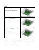
Mounting Sabertooth 2x32 has four mounting holes, which are sized for 4-40 machine screws. 5/8” Phillips machine screws are provided, but other lengths can be used as well. Sabertooth 2x32 has a single-piece machined heat sink. The heat sink features a pin-fin design, so it can be mounted in any orientation with acceptable thermal performance. The heat sink is not electrically connected to the electronics of the Sabertooth 2x32.
Drawings 3D models in IGES, STL and Solidworks formats are also available on Dimension Engineering’s web site. www.dimensionengineering.
Printable mounting diagram The following image is the same size as the Sabertooth 2x32. If this page is printed, it can be cut out and used as a template to drill the mounting holes. Remember when mounting to leave space for the input and output wires, and especially for a micro USB cable, if used. These are included for reference in the mounting diagram. www.dimensionengineering.