
Sabertooth Dual 25A Motor Driver User's Guide

Mode 1: Analog Input
Analog input mode is selected by setting switches 1 and 2 to the UP position. Switch 3 should be
either up or down, depending on the battery type being used. Inputs S1 and S2 are configured as
analog inputs. The output impedance of the signals fed into the inputs should be less than 10k
ohms for best results. If you are using a potentiometer to generate the input signals, a 1k, 5k or
10k linear taper pot is recommended. In all cases, an analog voltage of 2.5V corresponds to no
movement. Signals above 2.5V will command a forward motion and signals below 2.5V will
command a backwards motion.
There are three operating options for analog input. These are selected with switches 4, 5 and 6.
All the options can be used independently or in any combination.
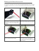
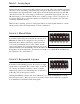
Switch 4: Mixed Mode
If switch 4 is in the UP position, the Sabertooth 2x25 is in
Mixed mode. This mode is designed for easy steering of
differential-drive vehicles. The analog signal fed into S1
controls the forward/back motion of the vehicle, and the
analog signal fed into S2 controls the turning motion of the
vehicle. If Switch 4 is in the DOWN position, the Sabertooth 2x25 is in Independent mode. In
Independent mode, the signal fed to S1 directly controls Motor 1 (outputs M1A and M1B) and
the signal fed to S2 controls Motor 2.
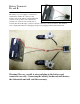
Switch 5: Exponential response
If switch 5 is in the DOWN position, the response to input
signals will be exponential. This softens control around the
zero speed point, which is useful for control of vehicles
with fast top speeds or fast max turning rates. If switch 5 is
in the UP position, the response is linear.
Utilizing the DEScribe software, this mode will allow you to create and implement a custom
throttle response curve. There are options to use Cubic, Linear, and Constant curve segments.
You will find more information later in this guide.
Switch 4: Mixed or independent
Switch 5: Exponential response