Sabertooth 2x25 V2 User’s Guide April 2012 Input voltage: 6-30V nominal, 33.6V absolute max. Output current: Up to 25A continuous per channel. Peak loads may be up to 50A per channel for a few seconds. 5V switching BEC: Up to 1A continuous and 1.5A peaks across the entire range of input voltages. Recommended power sources are: • • • • 5 to 20 cells high capacity NiMH or NiCd 2s to 8s lithium ion or lithium polymer.
Features Mixed and independent options: Sabertooth features mixed modes designed especially for differential drive robots, where two motors provide both steering and propulsion. It also has independent options in all operating modes. This is useful for if you have two motors to control, but they aren’t necessarily being used to drive a differential drive robot. The motors do not need to be matched or even similar, as long as they both are within Sabertooth’s operating limits.
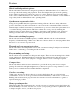
Hooking up the Sabertooth motor driver All connections to the Sabertooth are done with screw terminals. This makes it easy to set up and reconfigure your project. If you’ve never used screw terminal connections before, here is a quick overview. Step 1: Strip the wire which you are using approximately ¼”. The wires may be 12 gauge to 30 gauge. Use thicker wire for high current applications. Step 2: With a large screwdriver, turn the top screw counter-clockwise until it stops gently.
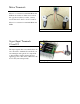
Battery Terminals B+ and BThe battery or power supply is connected to terminals B- and B+. B- connects to the negative side of the battery (usually black) B+ connects to the positive side of the battery The battery connects to terminals B+ and B(usually red or yellow). It is usually best to connect the battery through a connector instead of directly to the motor driver. This makes it easy to unplug the battery for charging, and prevents plugging in the battery backwards.
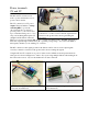
Motor Terminals Motor 1 is connected to terminals M1A and M1B as shown below. If the motor runs in the opposite way that you want, you may reverse the motor wires to reverse rotation. Motor 2 is connected to terminals M2A and M2B. The motors connect to terminals M1A/B and M2A/B Signal Input Terminals S1 and S2 The input signals that control the Sabertooth are connected to terminals S1 and S2.
Power terminals 0V and 5V The 0V and 5V connections are used to power and interface to lowpower control circuits. The 5V connection is a 5V power output. The 2x25 utilizes a 1 Amp switching BEC to power the onboard electronics as well as to The 5V terminal can be used to power small loads, like a provide power to your receiver and up to 4 standard analog servos. You potentiometer or a radio receiver.
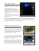
Status and Error LEDs Sabertooth 2x25 has three indicator LEDs. The blue LED marked Status1 is used to communicate various information about the current state. In most cases Status1 acts as a power indicator. In R/C mode, it glows dimly if there is no RC link present and brightly if there is an RC link. The blue LED marked Status2 is only used in lithium mode. It blinks to indicate the number of lithium cells detected.
Operating Modes Overview Mode 1: Analog Input Analog input mode takes one or two analog inputs and uses those to set the speed and direction of the motor. The valid input range is 0v to 5v. This makes the Sabertooth easy control using a potentiometer, the PWM output of a microcontroller (with an RC filter) or an analog circuit. Major uses include joystick or foot-pedal controlled vehicles, speed and direction control for pumps and machines, and analog feedback loops.
Lithium cutoff Switch 3 of the DIP switch block selects lithium cutoff. If switch 3 is in the down position as shown the Sabertooth will automatically detect the number of series lithium cells at startup, and set a cutoff voltage of 3.0 volts per cell. The Lithium Cutoff enabled number of detected cells is flashed out on the Status LED. If the number of cells detected is too low, your battery is in a severely discharged state and must be charged before operation.
Mode 1: Analog Input Analog input mode is selected by setting switches 1 and 2 to the UP position. Switch 3 should be either up or down, depending on the battery type being used. Inputs S1 and S2 are configured as analog inputs. The output impedance of the signals fed into the inputs should be less than 10k ohms for best results. If you are using a potentiometer to generate the input signals, a 1k, 5k or 10k linear taper pot is recommended. In all cases, an analog voltage of 2.5V corresponds to no movement.
Switch 6: 4x sensitivity If switch 6 is in the UP position, the input signal range is from 0V to 5V, with a zero point of 2.5V. If switch 6 is in the DOWN position, 4x sensitivity mode is enabled. In this mode, the input signal range is from 1.875V to 3.125V, with a zero point of 2.5V.
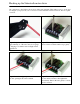
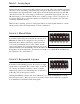
Mode 2: R/C Input R/C input mode is used with a standard hobby Radio control transmitter and receiver, or a microcontroller using the same protocol. R/C mode is selected by setting switch 1 to the DOWN position and switch 2 to the UP position. If running from a receiver, it is necessary to obtain one or more servo pigtails and hook them up according to figure 5.1. If there are only motor drivers being used it is acceptable to power the receiver or microcontroller directly from the Sabertooth as shown.
Switch 5: Exponential response If switch 5 is in the UP position, the response is linear. If switch 5 is in the DOWN position, the response to input signals will be exponential. This softens control around the zero speed point, which is useful for control of vehicles with fast top speeds or fast max turning rates. Exponential mode enabled Utilizing the DEScribe software, this mode will allow you to create and implement a custom throttle response curve.
A note on certain microprocessor receivers Some receivers, such as the Spektrum AR6000, will output servo pulses before a valid transmitter signal is present. This will cause the Sabertooth to autocalibrate to the receiver’s startup position which may not correspond to the center stick position, depending on trim settings. This may cause the motors to move slowly, even when the transmitter stick is centered.
Mode 3: Simplified Serial Mode Simplified serial uses TTL level single-byte serial commands to set the motor speed and direction. This makes it easy to interface to microcontrollers and PCs, without having to implement a packet-based communications protocol. Simplified serial is a one-direction only interface. The transmit line from the host is connected to S1. The host’s receive line is not connected to the Sabertooth. Because of this, multiple drivers can be connected to the same serial transmitter.
Option 1: Standard Simplified Serial Mode Serial data is sent to input S1. The baud rate is selected with switches 4 and 5. Commands are sent as single bytes. Sending a value of 1-127 will command motor 1 Sending a value of 128-255 will command motor 2. Sending a value of 0 will shut down both motors.
Mode 4: Packetized Serial Mode Packetized Serial uses TTL level multi-byte serial commands to set the motor speed and direction. Packetized serial is a one-direction only interface. The transmit line from the host is connected to S1. The host’s receive line is not connected to the Sabertooth. Because of this, multiple Sabertooth 2x25 motor drivers can be connected to the same serial transmitter.
Address Byte Configuration Address bytes are set by switches 4, 5 and 6. Addresses start at 128 and go to 135.
Commands The command byte is the second byte of the packet. There are four possible commands in packetized serial mode. Each is followed by one byte of data 0: Drive forward motor 1 (decimal 0, binary 0b00000000, hex 0h00) This is used to command motor 1 to drive forward. Valid data is 0-127 for off to full forward drive. If a command of 0 is given, the Sabertooth will go into power save mode for motor 1 after approximately 4 seconds.
6: Drive motor 1 7 bit (decimal 6, binary 0b00000110, hex 0h06) This command is used to drive motor 1. Instead of the standard commands 0 and 1, this one command can be used to drive motor 1 forward or in reverse, at a cost of lower resolution. A command of 0 will correspond to full reverse, and a command of 127 will command the motor to drive full forward. A command of 64 will stop the motor. 7: Drive motor 2 7 bit (decimal 7, binary 0b00000111, hex 0h07) This command is used to drive motor 2.
Setting Commands Several parameters of the Sabertooth 2x25 can be changed using Packetized Serial mode. Some of these changes persist when the unit is power cycled and some persist when it is switched to other modes. 14: Serial Timeout (decimal 14, binary 0b00001110, hex 0h0e) This setting determines how long it takes for the motor driver to shut off if it has not received a command recently. Serial Timeout is off by default. A command of 0 will disable the timeout if you had previously enabled it.
Checksum To prevent data corruption, each packet is terminated with a checksum. If the checksum is not correct, the data packet will not be acted upon. The checksum is calculated as follows: Checksum = address byte + command byte + data byte The checksum should be added with all unsigned 8 bit integers, and then ANDed with the mask 0b01111111 (decimal 127) in an 8 bit system.
DEScribe Software The Sabertooth 2x25V2 motor controller can interface with our DEScribe software. This software package allows you to change a lot about how the controller behaves both on the input and output sides.
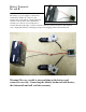
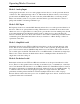
Appendix Figure 8.1: Fast and Intermediate Ramp Ramping Adjustment 1.8 1.6 Ramp Time (sec) 1.4 1.2 1 Intermediate Ramp Fast Ramp 0.8 0.6 0.4 0.2 0 0 10 20 30 40 50 60 70 80 90 Command Value Figure 8.