
User Guide

Status and Error LEDs
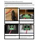
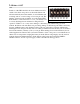
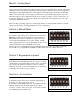
Sabertooth 2x12 has three indicator LEDs.
The green LED marked Status1 is used to
communicate various information about the
current state. In most cases Status1 acts as a
power indicator. In R/C mode, it glows dimly if
there is no RC link present and brightly if there
is an RC link.
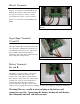
The green LED marked Status2 is used in
lithium mode. It blinks to indicate the number of
lithium cells detected. Also, when Status2 and
Error are flashing at the same time, and you are
experiencing no output from the motors, the unit
is displaying low voltage mode. Charge your
batteries first, and if that does not work, you will need a larger battery. Keep in mind that when
a lot of current is pulled from a battery, the voltage will drop. The more depleted the battery, the
worse the voltage drop. The Sabertooth will hold the unit in the error state for longer than the
battery voltage drops. This is to stop the unit from stuttering and gives the user enough time to
diagnose the flashing LEDs.
The red Error LED illuminates if the Sabertooth has detected a problem. It will light if the driver
has shut down due to overheating or overcurrent.
Mounting your Sabertooth 2x12
The Sabertooth is supplied with four mounting holes. These
can be used to attach it to your robot. The centers of the
mounting holes form a 1.5” x 2” rectangle. The holes are
.125 inches in diameter. The proper size screw is a 4-40
round head machine or wood screw. Four 5/8” long
machine screws and nuts are included.
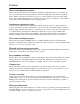
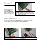
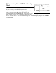
If your robot or device is constructed from insulating
materials such as wood or plastic, it may be necessary to
mount the Sabertooth on standoffs to allow air to circulate.
This is shown in Figure 2.3
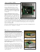
If your robot or device is constructed from metal, it is
usually better to attach the bottom heat spreader of the
Sabertooth directly to the frame, without standoffs. This
will allow your frame to act as a heat sink and will cause
the Sabertooth to run cooler. If your chassis is grounded,
you must insulate the heatsink from the chassis. This is
shown in Figure 2.4
Status1 LED on
Figure 2.3: Mounted to a wood
frame using standoffs
Figure 2.4: Mounted directly to a
metal frame