DELight tutorials. This document is meant to familiarize you with basic programming of the DELight lighting system. You can do much more with the system that what is described here. However, these tutorials are a good starting point for the commands and workflow. Start the DELink software. If you have a compatible piece of Dimension Engineering hardware connected, it will be automatically detected and the appropriate user interface will load.
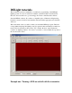
Lets say we want to create a very basic program. When the input is above half stick, the LED connected to channel 1 is on, and below half stick, the LED connected to channel 1 is off. This sort of program is common for things like landing lights. First, we need to create a program block at 100% brightness in the top track. We do this by clicking on the top track (it will highlight) then pressing the Add button. This will create a block with duration of one second, and brightness of 50%, as shown below.
At this point, if the program was loaded into a DELight controller, channel one would turn on above half stick, and off below half stick. Because the program repeats when it runs out of blocks, for this example the “Time” value of the blocks does not matter. Example two: Making a flashing LED Next, we are going to make an LED connected to channel two flash when the input is above 80% stick, and stay on continuously when the input is below 80% stick. Begin by selecting the Channel 2 tab.
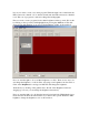
Next, highlight the top track again, and click Add again. This will create a second block. Change the brightness of this second block to 0%. At this point, we have a program that is on for one second and then off for one second. We’d like a faster flash rate than that, so we’ll have to change the time values of the blocks to .25 seconds each. Select the first block and type .25 into the box labeled Time as shown below.
Notice how the entry box went away as the block became too small to fit it. The duration of each block is represented on the horizontal axis. Because of this, you can also change the duration of a block by clicking on the vertical separator at the edge of the block and dragging it. Click the right edge of the 0% brightness block and drag it until it is the same width as the first block, as shown below.
Now, we would like to zoom in in order to see the blocks more closely. It is useful to use the zoom tools when editing long programs, or programs with rapidly-changing sections. Clicking the Zoom To Fit button will automatically scale the programs so they both fit on screen as shown below. The Zoom In and Zoom Out buttons work similarly. I’ve made the black box slightly too long, so should correct it to exactly .25 seconds by dragging or keying.
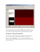
Finally, remember that we want this light to flash only when the input is above 80%. To change this, click on the slider labeled Trip Point and drag it to 80%. Trip Point is the value where the active track changes from the top track to the bottom track. The completed program is shown below.
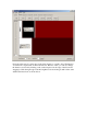
Simulator: Now, it would be useful to be able to preview the program as you have created it. You may do this by clicking on the Simulator tab. Simulator shows the outputs of all six channels. Notice how two of the channels are white, and the remaining channels are black.
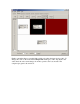
You can watch the behavior of your program with different inputs by dragging the slider at the right. This will act exactly like the lighting system would. Drag the input down to 40%. Notice that the box corresponding to Channel 1 turns from bright to dark, as shown below.
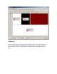
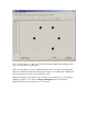
Now, drag the input up to 100%. Notice that the Channel 2 light begins flashing. In this way, you can preview your program. There are other things you can do with the Simulator. First, you can load a background image into it. Please note that these background images save with the files, which means they can make the save files several megabytes in size. Background images are useful if you are creating a scale model. Say you are creating a lighting program for a 777.
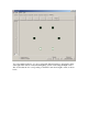
Now, say that we want the flashing Channel 2 to be a tail strobe. You can drag the images of the lights. Click on the Channel 2 light, and drag it to the tail, as shown. Drag the four dark lights into the corner so that they are not in your way.
If you change the color of the LEDs in their respective Channel tab, the color they display with in the simulator will also change. Example three: Making an LED glow. Channels 1 through 4 of the DELight controller are brightness-controllable. You can use this to create interesting glow type effects. We will create a light that increases in brightness for one second, and then decreases in brightness for one second. Select Channel 3, and create one top and one bottom block, both at 0% brightness.
Now, with the bottom track still selected, click the Add button to create a second block. Blocks create with the same time interval as the selected block, so it will also be .1 seconds. Zoom in and change the brightness of this block to 10%, Also, click on the Change button next to Light Color, and change the color to Green. This will not affect the color of the actual LED, but it does help keep track of which light is which inside the programming environment.
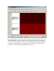
Add a third block, and set its brightness to 20%. Continue adding blocks until you have reached 100%. This will look like the following.
Now add another series of blocks with the brightnesses descending from 100% back to 10%. Remember that the tracks restart when they reach the end, so it is not necessary to put a 0% brightness block at the end. When you have completed all the blocks, click Zoom to Fit. You should have a track whose brightness increases and then decreases, as shown below.
This will create a light that fades in and out. Click on the Simulator to verify this is the behavior. If you want the fade in and out to be smoother, make the gradient using more blocks with more closely spaced brightnesses. However, remember that you are limited to 106 blocks on the controller. . Example four: Making alternating lights The output channels of the DELight controller are synchronized, so it is possible to make effects such as chaser lights or alternating police lights.
controlling smoke pumps, glow wire inverters or any other system which can take power from the RX. First, create two blocks of 0% brightness with duration of .5 seconds in the top track of both channels 5 and 6. Create a single block of brightness 0% in the bottom tracks of both channels. Make Channel 5 colored red, and Channel 6 colored blue. Channel 5 is shown below.
Now, you can see the top tracks of both channel 5 and channel 6 at the bottom of the screen. Notice that the blocks line up. To make alternating lights, we want one to be on when the other is off, and vise versa. Make the first block of channel 5 100% brightness, and the second block of channel 6 100% brightness, as shown below.
We now have police type lights that will come on about 50% stick. Remember that we created single 0% brightness blocks on the bottom tracks of channels 5 and 6. This means that below half stick, the police lights will be off. Drag the slider at right below 50% to activate the bottom two tracks, which will turn the lights off.
If you click on the Simulator, you will be able to see channel 5 and 6 alternate when the input is above 50%