DELight Programming Guide September 2008
Quiescent Draw: 15 mA LED Draw: 150 mA maximum apiece • Avoid connecting more than one LED to the controller when it’s being powered by your computer. Input Voltage: 6V recommended, 4-7.2v nominal • Runs off BEC power; make sure your BEC can handle it! LED Brightness: Up to 15 lumens Maximum Controller Commands: 94 Interface: USB Operating System: Windows 98, 2k, 2k3, NT, ME, XP, Vista Dimensions: DELight Controller: 28 x 22 x 5mm; 31cm pigtail; 6mm header; 6g 1.1” x .9” x .2”; 1’ pigtail; .25” header; .
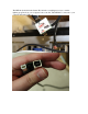
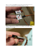
The DELink (included in the Starter Kit) includes everything necessary to transfer lighting programs from your computer to the controller. The DELink is connected to your computer through a USB port.
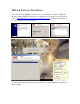
The servo connector of the DELight Controller (that would normally hook into your receiver) goes to the Plug header of the DELink, matching servo colors. LEDs hook in as shown below, with the red wire facing the Controller label. Your computer’s USB hub may not be rated for a lot of current, so only connect one LED at once when powered via USB.
DELink Software Installation The software for the DELight system is free to download and test, and is 7.7 MB. The interface is fully graphical, and we hope you will find it to be intuitive as well. It can be found at www.dimensionengineering.com/software/setup.exe. Starting the installation is as easy as running the downloaded file. Your firewall (or Windows Vista) may ask permission to allow DELink to install drivers. This is normal.
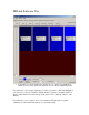
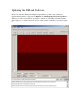
DELink Software Use • Commands on a given channel are divided into two tracks, Top and Bottom. Which is active at any given time depends on your throttle and the Trip Point. If your throttle or servo input (depending on where you plan to connect the DELight to your receiver) is above the channel’s Trip Point, the top track’s commands will be in effect for that channel; note that the trip point can be set to a different value for each channel.
Turn Off Below creates in effect a third trip point, below which the lighting on that channel is completely deactivated. You could, for instance, set your lights to turn on at 25% and flash above 75% throttle via Turn Off Below 25%, Trip Point 75%. No Signal Default sets which track the selected channel will run should you lose radio signal for any reason.
The Simulator gives an approximation of how the lighting setup will look. You can simulate loss of radio signal to see what happens if your radio encounters interference, hysteresis to give an indication of how far over the trip point you'll have to go to trigger a new pattern, and for intricate or fast designs, set it to display at 1/4 speed to see the timing shifts more clearly. The lighting channels are represented by the black squares.
Updating the DELink Software Every now and then, Dimension Engineering will have a patch to the software for upgraded functionality or bug fixes. If Options -> Automatically Check for Updates is enabled, you will occasionally be prompted to install one. Disabling automatic updates will require you to download a new version of the software each time you wish to update it.