
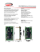
User Manual
Performance features
Output buffers
A bare accelerometer chip has an output impedance of 32kΩ, which is unsuitable for obtaining reliable
measurements when connected to an analog to digital converter. On the DE-ACCM6G, a dual rail to rail
operational amplifier buffers the outputs from the LIS244ALH, greatly reducing output impedance.
Buffer loading characteristics
For the purposes of this section, “max load” is defined as the resistive load that will cause a 2mV
drop in the output voltage at 0g. If your application does not require this level of accuracy, the DE-
ACCM6G can supply even more current at the cost of a larger drop in output voltage.
Max load is 0.83mA, or a resistance of 3kΩ
Supply filtering
A pair of resistors and a 0.1uF ceramic bypass capacitor on the DE-ACCM6G provide excellent power
supply decoupling. No external capacitors are necessary between Vcc and GND.
Output filtering and noise
A pair of 10nF capacitors limit the noise figure of the DE-ACCM6G, without overly sacrificing bandwidth.
RMS noise is typically 7.1mg, and output bandwidth is 500Hz - making it suitable for high frequency
sampling of acceleration.
Protection features
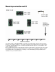
Reverse voltage
Even the best engineers sometimes get their wires crossed. In the event that you mix up VCC and GND, a P
channel MOSFET will prevent current from flowing – protecting the DE-ACCM6G from damage. This
protection is only designed to work with DC voltages. Do not apply AC voltages to the power pins.
Improper insertion
A resistor network ensures that the DE-ACCM6G will not be permanently damaged if you insert it backwards
(i.e. apply power to the output pins). The product will not function properly while it is used backwards. Do not
leave the DE-ACCM6G inserted backwards for more than 5 minutes at a time.
Output shorting
The operational amplifier driving the DE-ACCM6G’s outputs is capable of handling a direct short from the X
and Y outputs to ground for as long as you want.