
User Manual

Application hints LIS244ALH
12/16
4 Application hints
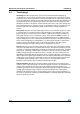
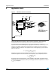
Figure 3. LIS244ALH electrical connection
Power supply decoupling capacitors (100 nF ceramic or polyester + 10
µF Aluminum)
should be placed as near as possible to the device (common design practice).
The LIS244ALH allows to band limit VoutX and VoutY through the use of external
capacitors. The recommended frequency range spans from DC up to 2.0 KHz. In particular,
capacitors are added at output VoutX and VoutY pins to implement low-pass filtering for
antialiasing and noise reduction. The equation for the cut-off frequency (f
t
) of the external
filters is in this case:
Taking into account that the internal filtering resistor (R
out
) has a nominal value equal to
110 KΩ, the equation for the external filter cut-off frequency may be simplified as follows:
The tolerance of the internal resistor can vary typically of
±20% within its nominal value of
110 KΩ; thus the cut-off frequency will vary accordingly. A minimum capacitance of 1 nF for
C
load
(x, y) is required.
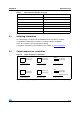
Digital signals
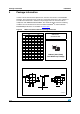
LIS244ALH
(top view)
(TOP VIEW)
DIRECTIONS OF THE
DETECTABLE
ACCELERATIONS
Y
1
X
ST
GND
1
4
9
12
Vdd
GND
GND
100nF
10
µ
F
Vout y
Cload Y
Vout x
Cload X
5
16
2
3
67
8
10
11
15 14 13
FS
PD
Pin 1 indicator
Optional
Optional
f
t
1
2π R
out
C
load
xy,()⋅⋅
---------------------------------------------------------------- -=
f
t
1.45µF
C
load
xy,()
-------------------------------
Hz[]=