Model X Mechanical Force Gauge User Instructions 16949-0018 Issue AH
© Avery Weigh-Tronix, LLC 2012. All rights reserved. No part of this publication may be reproduced, stored in an electronic retrieval system, or transmitted in any form or by any means, electronic, mechanical, photocopying, recording or otherwise without the prior written consent of the copyright owner, or as permitted by law or under license. Full acknowledgment of the source must be given. Avery Weigh-Tronix is a registered trade mark of the Avery Weigh-Tronix, LLC.
Table of Contents page Chapter 1 General information and warnings ......................................................................................... 5 About this manual .............................................................................................................. 5 Special messages .............................................................................................................. 5 Safe Operation ..............................................................................
Model X Mechanical Force Gauge User Instructions
1.1 1 General information and warnings 1.1 About this manual About this manual This manual is divided into chapters by the chapter number and the large text at the top of a page. Subsections are labeled as shown by the 1.1 and 1.1.1 headings. The names of the chapter and the next subsection level appear at the top of alternating pages of the manual to remind you of where you are in the manual. The manual name and page numbers appear at the bottom of the pages. 1.
General information and warnings Although this instrument has a substantial overload protection rating, the instrument should not be used above the rated capacity. Doing so can significantly impact fatigue life of the instrument and cause premature and abrupt failure. If a higher capacity reading is needed, Dillon insists that a larger instrument be used. Safety is always a concern in overhead lifting and tensioning applications.
1.5 1.
General information and warnings 1.6 Declaration of conformity Only the 5,000kg Force Gauge with Klaxon alarm is CE approved.
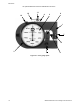
2.1 2 Introduction 2.1 General description General description The Model X mechanical force gauges measure tension, compression or push/pull. A D-shaped deflection beam is the heart of the Model X force gauge. Machined to close tolerances, beams are heat treated to develop optimum strength and spring characteristics. A precision dial indicator is mounted on the deflection beam. The indicator plunger rests against a slanted anvil at the open end of the beam.
Introduction *An optional Maximum Pointer is available but not shown 12 10 11 4 2 8 1 7 5 3 9 6 Figure 2.
2.3 2.3 Klaxon alarm option Klaxon alarm option Only the 5,000kg Force Gauge with Klaxon alarm is CE approved. All other models are not CE approved. The force gauge can be attached to an optional klaxon alarm. See Figure 2.2. Rear View Front View Alarm switch adjustment screw Force Gauge with optional klaxon alarm Test Button: Press to test horn function Figure 2.2 Force gauge with optional klaxon alarm The klaxon alarm is rated at 80db(A) @ 0.6 meters (2 feet).
Introduction 2.4 Operational data WARNING: Never pick up the force gauge by the dial indicator. This will cause loss of calibration accuracy, loss of operation or non-warranty damage. Your Dillon Force Gauge is ready to go to work for you without any special assembly. Upon removing it from the storage case, it is only necessary to check the zero setting. 1. Place the unit on a flat table with the pressure button, #4, at the top. 2. The dial bezel, #3, is locked lightly by a knurled thumb screw, #10.
2.5 Helpful pointers l Note that threaded mounting holes have been provided in opposite faces of the “U” shaped deflection beam, #1. In the upper mounting hole, a spherically recessed pressure button, #4, is screwed. This button is hardened and plated. It receives the loading ball, #11. Force should be applied directly against this ball. In operation, the deflection beam bends inward slightly, and the ball revolves, tending to keep the line of force vertical.
Introduction 2.6 Tensile Model Generally speaking, the same requirements and suggestions applying to the compression model force gauge also apply to the tensile unit, shown in Figure 2.3. The main exception, of course, is that on the tensile model, load is applied through the use of special end rod bearings. Figure 2.3 Tensile model with adapters and shackles These bearings are available for all tensile models as standard equipment. They are a perfect fit and without any side play.
2.7 Push-Pull model Do not attempt to weld, cotter pin, or otherwise make tensile connectors a solid part of the bar since every requirement is different as to the length of the shank that has to be used. Dillon will not be liable for any incident that might result from accidental or intentional screw-out or break-away of the ball-socket connectors. For your own protection, keep these parts properly seated at all time.
Introduction 16 Model X Mechanical Force Gauge User Instructions
AUTHORIZED DISTRIBUTORS Ask the experts. Dillon distributors offer complete service capabilities from application assistance to sales and product support. Their experienced representatives are the most knowledgeable experts that you will find in the force measurement industry. We recommend that you consult these capable specialists for all of your measuring needs. Overload Protection and Overhead Weighing Equipment 1000 Armstrong Drive Fairmont, Minnesota U.S.A.