
Manual

When you have determined that
your adjustments are correct, tighten
the lock ring (#14067). Fig. 16
Powder Bar Return Rod Assembly
The purpose of the powder bar
return rod is to return the powder bar
to its closed position.
Remove the blue cap from the pow-
der die (#20320) and loosely clamp the
powder measure in position.
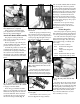
To install the powder bar return rod
(#13960) remove the blue wing nut
(#13799) and rod spring (#14033) from
the rod, then insert the bottom end
through the 3/8” eyebolt (#13089) that
is mounted on the left rear of the main
frame.
Next, using your thumb and index
finger of your left hand, move the lock-
link down and align the hole with the
slot on the bellcrank. Then, insert the
rod through the two holes and insert
the return rod clip (#13929). Fig. 17
Install the spring (#14033) and wing
nut (#13799) on the rod and screw the
wing nut up until you feel light tension
on the spring. Fig. 18 Tighten the pow-
der measure clamp screws (#14037).
You will notice an adjusting bolt on
the front of the powder bar. Counter-
clockwise reduces the powder charge,
clockwise increases the charge. Fig. 19
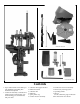
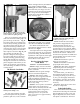
Your machine comes with two pow-
der bars. Fig. 20 One large (#20063)
and one small (#20062). Rule of thumb:
Use the large bar whenever possible.
Index a sized and primed case under
the measure and operate the machine’s
handle. Turning the powder bar adjust-
ment bolt clockwise increases the pow-
der charge – counterclockwise turns
decreases the powder charge. By trial
and error, determine the correct weight
of your powder charge by using a pow-
der scale. Fig. 19
When the correct powder charge
had been set, cycle several cases
through the machine and check the
load with a scale.
Primer Magazine
Select the proper size primer pick-up
tube and fill it by placing the plastic tip
over loose primers and pressing down.
You will notice that the primer maga-
zines and primer pick-up tubes have
different colored tips. They have been
color coded to help you identify size
more easily.
The color code is as follows:
Blue Small Primer Magazine
Orifice
Red Large Primer Magazine
Orifice
Yellow Small Primer Pick-up Tube
Green Large Primer Pick-up Tube
The shiny side of the primers should
be facing up. This is most easily accom-
plished by use of a primer flip tray. Fig.
21 This quality cast metal flip tray is
available from Dillon Precision and is a
better choice than the smaller plastic
trays which are difficult to use and
have a tendency to warp.
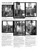
Fig. 16 - Be sure to tighten the lock ring
when adjustments are completed.
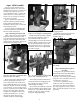
Fig. 17 - Install the return rod clip to secure
the powder bar return rod. See the schemat-
ic on page 31 for more details.
Fig. 18 - See the schematic on page 31 for
more details.
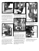
Fig. 19 - Clockwise turns of the powder bar
adjustment bolt increase the powder charge
while counterclockwise turns decrease the
powder charge.
Fig. 20 - Small powder bar (left), large pow-
der bar (right).
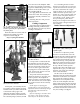
Spacer
Fig. 21 - All of the primers must be shiny
side up.
9