
Manual
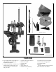
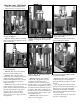
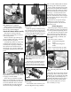

The casefeed mounting post assem-
bly (#20641) is attached to the case-
feed post studs (#13271) by the use of
two post bolts (#13205). Attach the
power cable and clamp and bin brack-
et (#12144) as shown in the schematic
on page 30. Fig. 6
The casefeed bowl assembly needs
to be placed on the casefeed post with
the Dillon logo and the on/off switch
facing you.
The casefeed tube (#13761) should
now be inserted into the casefeed
adapter (#13654*) Fig. 7 Note that
the tube is marked “up” on one end.
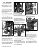
Press this end into the tube clip
(#13859) attached to the casefeeder
motor housing Fig. 8. This assembly
is now complete.
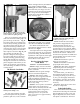
Step 3: Installing the Powder Measure
Remove the blue cap from the pow-
der die (#20320) and loosely clamp the
powder measure in position. Fig. 9
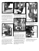
Install the powder measure return rod
(#13960) through the 3/8” eyebolt
(#13089) mounted on the left rear of the
main frame. Fig. 10 Now attach the rod
to the powder measure bellcrank using
the clip. Fig. 10 Install the spring
(#14033) and wing nut (#13799) on the
rod and screw the wing nut up until
you feel light tension on the spring.
Tighten the powder measure clamp
screws (#14037).
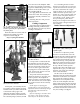
Step 4: Installing the Spent Primer
Cup and Bullet Bin
Install the spent primer cup (#13650)
on the right side as shown on the
schematic on page 27. Fig. 11
7
Fig. 6 - Shown is the proper position of the
power cable, clamp, and bin bracket.
Fig. 7 - The proper location and positioning
of the casefeed tube and adapter is as
shown above.
Fig. 8 - The end of the casefeed tube marked
“up” snaps into the clip at the base of the
casefeeder motor housing.
Fig. 9 - See arrow. A slight gap allows the
powder die to be adjusted without removing
the powder measure.
Fig. 10 - Note how the spring above the
wing nut is slightly compressed.
Clip
Spring
Fig. 11 - See the schematic on page 27 for
more details.