
Manual

Super 1050 Assembly
Your new Super 1050 has been
assembled at the factory. All of the
adjustments necessary to reload have
already been made, in fact we’ve
even adjusted the dies to reload the
caliber you have chosen. However,
before you can reload you must do
some minor assembly.
Due to variations in components,
check all stations for proper settings
before loading ammunition. It is
absolutely necessary that you read the
following instructions.
If you get stuck on something that
you don’t understand, call (800) 223-
4570 for technical assistance.
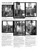
Step 1: Mounting the Super 1050
Select a clear area on your reloading
bench. Be certain your bench is free
from vibration and is strong enough to
support your Super 1050’s mass and
operating force. If possible, attach your
bench to the wall using screws.
Remove the Super 1050 main frame
from the packaging and place it on
your selected area. The crank exten-
sion (#11000) should be to your right.
Bring the machine to the forward edge
of your bench – be sure to allow clear-
ance for operation of the handle. Mark
the four mounting holes using the
machine as a template. Remove the
machine and drill four 1/4” holes
through the bench. Replace the
machine and bolt securely. Fig. 1
Install the handle (#12727) as indicat-
ed in the parts schematic. Secure in
place with the handle set screw
(#13432). Fig. 2 You will note that there
are three different positions for mount-
ing the operating handle. Choose the
one that feels best for you. The longer
the handle, the less force required but
the stroke is longer.
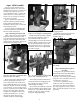
The toolhead (#20420) is held down
on the main frame for shipping by the
use of plastic ties. Remove the ties
while holding the handle.
Slowly move the handle up. This will
move the toolhead approximately three
inches to its “up” position. Note: If the
handle is not moving freely, carefully
inspect for shipping damage.
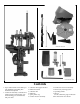
Install the six brass locator buttons
(#20637*) around the shellplate
(#12600*). Fig. 4
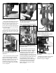
Step 2: Installing the Casefeed
Assembly
Using the screw provided (#13377)
install the bin bracket (#13238). Fig. 5
Install the bullet bin bracket
(#12144) to the casefeed post (#20641)
using the screw (#13685) as shown in
the schematic on page 30.
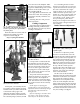
Screw the casefeed post studs
(#13271) to the main frame (place
the washer provided on the bottom
post only), tighten securely with an
Allen wrench through the cross hole
provided.
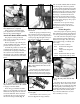
Fig. 1 - Be sure the machine is to the for-
ward edge of the table or bench when mark-
ing the four holes to be drilled.
Fig. 2 - Note that there are three different
positions for mounting the operating handle.
Fig. 3 - Be sure to hold the operating handle
in place while cutting the plastic ties.
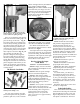
Fig. 4 - Locator button being inserted into
its proper position.
Fig. 5 - See the schematic on page 30 for
more details.
6