
Manual

23
10999
11000
11008
10994
11008
13685
11010
10996
11002
11009
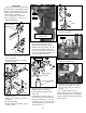
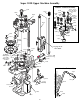
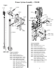
Lube Points for the Super 1050
Crank Assembly
With the handle in the rest position,
on the left side of the machine, use a
grease syringe to lube the bearing pin
(#11009) located in the link arm
(#11002). Then, cycle the handle down
to the bottom stop.
Again, using the grease syringe,
lube the mainshaft pivot pin (#10994)
on the left side of the machine via the
access hole located 1.2" above the car-
rier cap (#11010).
Use 30 weight motor oil on the main-
shaft (#10999).
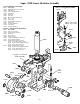
Towards the back of the machine,
lube the indexing lever cam surface
(#20312) and index lever shoulder
bolt (#13276).
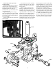
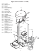
When it is time to lube the roller
bearings (#11008) in the frame and
crankshaft, first remove the swage rod
assembly, swage connecting rod, and
operating handle. On the left side of the
machine, use a 5/32" Allen wrench to
remove the screw (#13685). Slide the
carrier cap (#11010) out of its bore and
lube the left-hand side roller bearing
(#11008) and carrier cap. Next, slide the
crankshaft (#11000) out of the frame
from the right side of the machine BUT
NO MORE THAN 3/4". Using a grease
syringe, dispense some grease onto the
right-hand side roller bearing (#11008).
Next, lube the crankshaft surface
(#11000). Then, reinsert the crankshaft
fully into the frame. Reinstall the carrier
cap (#11010). Blue Loctite must be used
on the threads before installation, tight-
en. Finally, reassemble the swage com-
ponent and operating handle back onto
the frame. Lube the swage connecting
rod (#13417) and clevis pin (#13522).