
Manual

sure everything is properly located.
With the handle in the down position,
tighten the toolhead bolt with the
above mentioned wrench.
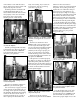
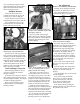
Shellplate Removal
Loosen the ejector tab screw
(#13896) and swing the ejector tab
(#13189) out of the way. Fig. 38
Loosen the four locator tab screws
(#13895) about four full turns. Fig. 37
Use a toothbrush to remove any
powder that may be in the threads
before removing the lock ring.
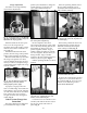
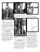
Next remove the lock ring (#20311).
Now push the casefeed plunger back
(#13073*) and lift the shellplate off. Be
sure to lightly grease the bore of the
shellplate when reinstalling it. Fig. 44
Rule of thumb: turn the lock ring
down until tight then back off one-
eighth of a turn. Then tighten the four
locator tab screws (#13895).
Casefeed Plunger Conversion
When changing calibers it may be
necessary to replace the casefeed
plunger (#13073*).
To do this, remove the clear casefeed
tube (#13761) and pull out the colored
casefeed adapter (#13654*). The adapter
is taped for shipping purposes.
Remove the two housing screws
(#13815) and the casefeed adapter
housing (#11006).
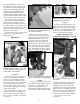
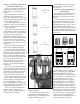
Place your hand on the plunger
while removing the roller bolt (#13333).
This will prevent the casefeed plunger
and spring from jumping out of the
machine. Fig. 45
Thoroughly clean the track and
casefeed parts with a solvent. Now
very lightly apply grease to the sides
and install the proper size casefeed
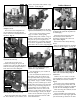
plunger (#13073*). Fig. 46 Remember
to grease the roller (#13498) and the
roller track (Fig. 46) and Loctite the
threads on the roller bolt (#13333).
Install the casefeed housing and
insert the proper size adapter (#13654*).
The casefeed tube (#13761) should now
be inserted into the casefeed adapter
(#13654*). Note that the tube is marked
“up” on one end. Press this end into the
tube clip (#13859). See the Trouble
Shooting section for any adjustments.
Die Adjustments
Station 2 - To install the size/decap die
Warning: Never attempt to deprime
live primers, an explosion may result.
Move the toolhead down, by lower-
ing the handle all the way down.
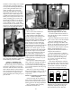
Screw the sizing die into Station 2.
Continue to screw the die down until it
just touches the shellplate. Fig. 47
Tighten the die lock ring finger tight.
Now move the toolhead up by raising
the handle to its upright position.
Note: When loading .270 or .30-06
you need to raise the decap assembly
so that the hitch pin clip is a minimum
of 1/8” above the silver lock ring as
shown in Fig. 47.
Place a case in the casefeed funnel.
Here, the case drops to the casefeed
plunger.
Cycle the handle. The casefeed cam
pushes the roller bushing back, drop-
ping the case into the slot of the
plunger.
Cycle the handle. The case is inserted
into the shellplate.
Note: After raising the handle,
insure that you push the handle
against its full aft stop. This will
insure that the shellplate fully
advanced to the next station.
Note: When priming, pushing the
handle against its stop, will insure that
the primer is fully seated.
15
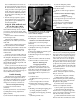
Fig. 45 - The casefeed plunger and spring
are under tension. Hold them in place while
removing the roller bolt.
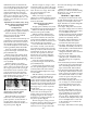
Fig. 44 - Your machine will work its best
when properly cleaned and lubricated.
Fig. 46 - Be sure to lightly grease the sides
of the casefeed plunger track, casefeed
plunger and roller after cleaning.
roller track
Fig. 47 - Screw the size/decap die down
until it just touches the shellplate.