
Manual

Swage Adjustments
Use ONLY an unswaged military
case for these adjustments.
With the handle in the down posi-
tion, screw the swage back-up
expander down until it makes contact
with the case bottom and holds it in
place. Fig. 31
With the handle still in the down
position, turn the swage rod up until it
makes contact with the case bottom.
Raise the handle half-way and rotate
the swage rod a quarter turn. Now,
cycle the handle. Inspect the case and
when you achieve a completed swage
of the primer pocket, tighten the swage
lock nut (#14067).
Aproperly swaged pocket will
show a rounded edge around the rim.
Some military cases (.223 & .308) start
out with three small dents around the
base of the pocket, once properly
swaged, the dents will no longer be
visible. Fig. 32
Primer System Change Over
Instructions
The Super 1050 has been shipped to
you with either the large or small
primer system installed. To change the
system from large to small or vise
versa, follow these instructions:
Be sure all primers have been
removed from the primer system. Then
remove the Early Warning System and
the knurled cap. Then remove the
primer magazine (#22031 - large or
#22030 - small) and replace it with the
new size magazine. Be sure the key on
the tip (#14003 - large or #14024 -
small) is in the slot and the magazine is
all the way down in place. Fig. 33
Pull the operating handle to its down
position.
Loosen the lever arm bracket screw
(#14037) and slide the bracket assem-
bly up four inches and lock it in
place. Fig. 34
Raise the operating handle, remove
the two primer feed body screws
(#13363) and lift off the primer feed
body assembly (#20773).
Remove the powder bar return rod
(#13960) from the powder measure
bellcrank (#17839) by releasing the
return rod clip (#13929). Fig. 35
Remove the casefeed tube (#13761)
and place it on your bench. Remove
the toolhead. Fig. 36 For more infor-
mation see the following section –
TOOLHEAD REMOVAL.
13
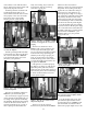
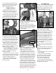
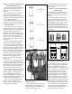
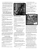
Fig. 32 - Note the difference between the
swaged primer pocket (left) and the
unswaged primer pocket (right).
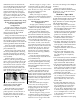
Fig. 31 - A cut-a-way view of a .45 ACP with
the swage rod and the back-up rod properly
adjusted in the swaging position.
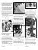
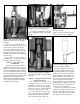
Fig. 33 - Note the shape of the key at the
base of the primer magazine tip.
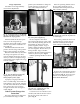
Fig. 34 - Slide the bracket assembly up and
out of the way – retighten the lever arm
bracket screw to hold it in place.
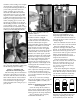
Fig. 35 - After removing the clip and discon-
necting the rod, replace the clip in the rod
for safe-keeping.
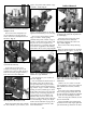
Fig. 36 - To remove the toolhead unscrew
the toolhead bolt and remove.