
Manual

ple height adjustment to the seating
stem may be necessary. Refer to a load-
ing manual for proper loaded length
(OAL). Cycle the handle again and
check for crimp at Station 8. Refer to
Trouble Shooting item 8 for adjust-
ments if necessary. Add a bullet, cycle
again. Your first loaded round should
now be ejected into the collection bin.
If all has gone well to this point
you’ve got it made. Just keep adding
bullets, watch your fingers so they
don’t get caught and don’t hurry. Just
try to be smooth in your operation. The
speed will come naturally and you’ll be
doing a thousand rounds per hour
before you even realize it.
The following are some adjustment
suggestions as well as Trouble
Shooting hints.
Adjustments
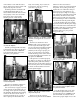
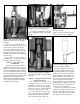
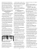
Casefeeder
It may be necessary to readjust the
micro-switch for different calibers.
Cases may become lodged between
the micro-switch and the tube wall.
The other extreme is the case failing to
put enough pressure on the micro-
switch to shut off the system causing
it to continue running and over flow-
ing the tube. Fig. 26
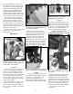
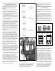
The casefeed spacer (#13703) sup-
plied in the accessory package, is to
be used when you are reloading .41
Mag, .44 Mag, .357 Mag, .30 Carbine,
or .45 Colt.
Remove the two clutch screws
(#13732), lock washer (#13813) and
upper clutch (#13632) and the case-
feed plate. Place the spacer on the
shoulder of the lower clutch and
reassemble – see the schematic on
page 31 for more details. The casefeed
plate should now be approximately
1/8” above the floor of the casefeed
bowl. Note: Make sure the casefeed
plate is centered in the bowl. Fig. 27
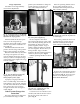
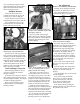
Handle
The operating handle is adjustable to
three different length settings. Choose
the one most comfortable for your
operation. Loosen the set screw
(#13432) then retighten when the han-
dle is in the most comfortable position.
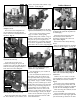
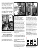
Swager
Swaging on the Super 1050 is a sim-
ple process and is necessary on all car-
tridge cases as a means of uniforming
the entrance of the primer pocket. Fig.
29 The swage rod (#20314 large or
#20313 - small) is fully adjustable.
Swage Conversion and
Adjustment Conversion – Fig. 30
Begin by removing the swage cover
(#13064). Next remove the hitch pin
(#13840) and slide out the clevis pin
(#13522). Remove the operating handle.
Rotate the swage connecting rod a half
turn and remove it. This will allow you
access to the swager. Pull the swager
down and out of the machine. Fig. 30
Insert the new swager and
reassemble.
12
Fig. 26 - Shown is the micro-switch that
automatically shuts off when a case is next
to it. Also shown is an optional spacer for
certain calibers: .380 and 9mm.
Micro-switch
Spacer
Fig. 27 - Make sure the casefeed plate is
centered in the bowl with approximately
1/8” all the way around.
Fig. 30 - See the schematics on page 28 for
more details.
Fig. 29 - Note the difference between the
swaged primer pocket (left) and the
unswaged primer pocket (right).
Fig. 28 - Note that there are three different
positions for mounting the operating handle.
1/8”