Super 1050 Instruction Manual Version 1.1 illon recision Products, Inc.
Table of Contents Contents 4 How the Super 1050 Works: Stations 1 - 8 5 Super 1050 Assembly 6 Powder Measure Adjustment 8 Primer Magazine 9 Electric Casefeeder 10 Review: How the Super 1050 Works: Stations 1 - 8 10 To Begin Reloading 10 Adjustments 12 Primer Seating Depth - Station 4 11 Casefeeder 12 Handle 12 Swager 12 Swage Conversion & Adjustment 12 Primer System Change Over Instructions 13 Toolhead Removal 14 Shellplate Removal 15 Casefeed Plunger Conversion 15 Die Ad
Warranty Agreement The Dillon Super 1050 reloader has been designed as a commercial machine. Our expectation is that its life expectancy will be in excess of two million rounds of loaded ammunition. All Super 1050 machines are warranted for life from defects in material or workmanship, plus a one-year, 100% warranty against normal wear. All electrical/electronic components in Dillon equipment are covered by a one-year warranty.
items not to scale items not to scale Contents • Super 1050 machine with caliber specific shellplate and loading dies installed and adjusted.
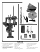
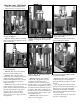
How the Super 1050 Works Stations 1 - 8 (counterclockwise) toolhead and dies cut away for clarity Station 1 - The casefeed plunger inserts the case into the shellplate. Station 1: Empty cases are automatically inserted into the shellplate via the electric casefeeder. Station 7 - In this station, the bullet is seated to its proper depth. Station 3 - Here the case mouth is expanded while a rod supports the case base for swaging. Station 7: The bullet is seated to its proper depth at this station.
Super 1050 Assembly Your new Super 1050 has been assembled at the factory. All of the adjustments necessary to reload have already been made, in fact we’ve even adjusted the dies to reload the caliber you have chosen. However, before you can reload you must do some minor assembly. Due to variations in components, check all stations for proper settings before loading ammunition. It is absolutely necessary that you read the following instructions.
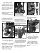
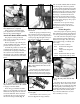
Clip Fig. 6 - Shown is the proper position of the power cable, clamp, and bin bracket. The casefeed mounting post assembly (#20641) is attached to the casefeed post studs (#13271) by the use of two post bolts (#13205). Attach the power cable and clamp and bin bracket (#12144) as shown in the schematic on page 30. Fig. 6 The casefeed bowl assembly needs to be placed on the casefeed post with the Dillon logo and the on/off switch facing you. Fig.
travel forward to the shellplate. Make sure that you repeat this several times to gain an understanding of the various functions of the machine before you start reloading. Fig. 13 Now plug in the casefeed motor and activate the switch. The casefeed plate should turn smoothly within the casefeed bowl. Assuming that all is well, proceed with components. Loading Components Fig. 12 - Shown is the proper location of the cartridge collection bin.
Fig. 16 - Be sure to tighten the lock ring when adjustments are completed. When you have determined that your adjustments are correct, tighten the lock ring (#14067). Fig. 16 Powder Bar Return Rod Assembly The purpose of the powder bar return rod is to return the powder bar to its closed position. Remove the blue cap from the powder die (#20320) and loosely clamp the powder measure in position.
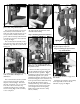
caliber cartridges that may be hidden in larger caliber cartridges. Fig 23 Warning: Be sure that no loaded rounds are mixed with your empty cases. It is possible to feed a blunt nosed cartridge like a .38 Sp. WC into the shellplate upside down and explode it when it is hit by the decap pin. Fig. 22 - When installing primers into the primer magazine, be sure the pick-up tube centers itself before pulling the clip.
will continue to run until the tube is full, at which point a micro-switch will temporarily stop the case flow. From this point the casefeeder will automatically fill the tube as you reload. If the casefeeder does not function properly or the cases do not fall base down, refer to the Trouble Shooting section of this manual. ready it for seating. If you count one second down, and one second up, you’ll have a good pace. 5. Remove the locator button (#20637*), extract the round and check the primer.
ple height adjustment to the seating stem may be necessary. Refer to a loading manual for proper loaded length (OAL). Cycle the handle again and check for crimp at Station 8. Refer to Trouble Shooting item 8 for adjustments if necessary. Add a bullet, cycle again. Your first loaded round should now be ejected into the collection bin. If all has gone well to this point you’ve got it made. Just keep adding bullets, watch your fingers so they don’t get caught and don’t hurry.
Swage Adjustments Use ONLY an unswaged military case for these adjustments. Fig. 31 - A cut-a-way view of a .45 ACP with the swage rod and the back-up rod properly adjusted in the swaging position. With the handle in the down position, screw the swage back-up expander down until it makes contact with the case bottom and holds it in place. Fig. 31 With the handle still in the down position, turn the swage rod up until it makes contact with the case bottom.
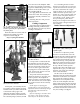
replace, the primer slide (#20318 - large or #20317 - small). Fig. 39 Fig. 37 - The four lock ring screws need only be loosened about four turns to remove the shellplate lock nut. Now remove the shellplate lock nut (#13425) by loosening the four locator tab screws (#13895) about four full turns. Fig. 37 Fig. 40 - A special screwdriver for the bushing has been included in your accessory bag.
Die Adjustments sure everything is properly located. With the handle in the down position, tighten the toolhead bolt with the above mentioned wrench. Station 2 - To install the size/decap die Warning: Never attempt to deprime live primers, an explosion may result. Move the toolhead down, by lowering the handle all the way down. Shellplate Removal Loosen the ejector tab screw (#13896) and swing the ejector tab (#13189) out of the way. Fig.
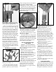
Fig. 49 - You don’t need any more expansion than what you see in this photograph. A properly expanded case should show a slight flare at the case mouth. Fig. 49 Fig. 51 - This photo shows the powder bar at the end of its travel. white cube must contact the powder measure body (see arrow FIG 51). Fig. 48 - As the toolhead continues down, it will reshape the case neck, shoulder and body. Again, move the toolhead down. The case is now sized. If the case has a spent primer, it will be deprimed.
Station 5 - Adjustment of the Powder Die/Powder Funnel Cont... Drop a case into the casefeed funnel and cycle the handle twice. The case should now be in the shellplate at Station 2. Move the handle down. Notice the resistance at the end of the down stroke. This is the resistance of the case in the sizing die. Raise the handle. The case will index to Station 3. Cycle the handle to advance the case to Station 4. Again, cycle the handle to prime the case and index it to Station 5. Cycle the handle.
schematic of the cartridge. For example, .38 Special lists a maximum OAL of 1.55" (Lyman Reloading Handbook). If you’re seating the bullet to the cannelure/crimping groove, the OAL should be well within the maximum OAL listed, however, use a set of dial calipers to check it. (Dial calipers are available from Dillon Precision). If the bullet you’re using doesn’t have a cannelure/crimping groove, refer to the specific type of bullet you’re using in the reloading manual.
defined line below the mouth of the case and the bulge below the line. This is not a proper crimp. This line is the direct result of the cartridge being over crimped. A line like this will only appear if the crimp die is adjusted down too far. Warning: Over crimping .45ACP, .38 Super, 9mm, etc., can actually cause the bullet to be loose in the case. Turn the swager in, using 1/4 turn increments until you achieve the proper swage. Secure the jam nut (#13682). Note: Do not over swage.
has an additional bend in it but can be used on both the Super 1050 and RL 1050 machines. NOTE: If you are using an indexer return spring from an RL 1050 spare parts kit, you will need to make an additional bend in the spring before installing it on the Super 1050. • The RL 1050 spent primer cup has been replaced with a larger, plastic spent primer cup and bracket. It is not interchangeable. 5.) Bent or broken shellplate (#12600*). Using RL 1050 toolheads and dies on the Super 1050...
case has been flattened out. 2.) High primers: a.) Adjust the primer push rod (#12819). b.) On .223 cases the swage back-up rod (#13332) is down too far, slightly collapsing the primer pocket and not allowing the primer to seat fully. c.) Loose shellplate (#12600*). d.) Erratic handle motion. e.) Do not remove the rubber piece on the primer slide. 3.) Smeared primers - see Station 3: Primer Pocket Swaging - item 1 4.) Locator tab: a.
Lubrication Operating circumstances will dictate the frequency of required lubrication. It is highly recommended that the Super 1050 be cleaned and lubed after every 10,000 rounds of operation. Use a high-grade, conventional wheel bearing grease – do not use oil.
Lube Points for the Super 1050 Crank Assembly With the handle in the rest position, on the left side of the machine, use a grease syringe to lube the bearing pin (#11009) located in the link arm (#11002). Then, cycle the handle down to the bottom stop. Again, using the grease syringe, lube the mainshaft pivot pin (#10994) on the left side of the machine via the access hole located 1.2" above the carrier cap (#11010). Use 30 weight motor oil on the mainshaft (#10999).
RL 1050 - Caliber Conversion Chart 20477 – .38/.357 Conversion 20482 – 9mm Conversion 12704 14062 13137 13802 13098 17384 13569 14067 13005 12938 14060 12833 13878 13306 17384 13569 14067 13005 #2 Shellplate #2 Locator Buttons (6) .38/.357 cal. Expander – D Adapter – Orange Casefeed Plunger – Medium Blue Locator Tab – Short (1) Blue Locator Tab (5) Die Lock Ring Powder Activator – Pistol #5 Shellplate #3 Locator Buttons (6) 9mm cal.
Super 1050 - Caliber Conversion Chart The Super 1050 loads all of the calibers listed for the RL 1050 as well as the calibers listed below. #21049 – .308 Conversion #21053 – .270 Conversion 11005 12074 12184 12999 13073 13483 13569 13587 13930 14067 17384 11004 12069 12184 12999 13073 13456 13483 13569 13930 14067 17384 Super 1050 Adapter - .308 Win Back-up Expander - .
Super 1050 Parts Listing Part # 10991 10992 10993 10994 10995 10996 10997 10999 11000 11001 11002 11003 11006 11008 11009 11010 11011 12144 12184 12260 12486 12572 12819 12930 12972 12995 13001 13058 13064 13073 13089 13091 13098 13108 13161 13189 13205 13226 13238 13244 13245 13262 13271 13276 13296 13306 13333 13335 13342 13363 13377 13417 13419 13426 13432 13435 Description Bin Support Bracket Inside Frame Stop Spent Primer Cup Bracket .560 dia.
Super 1050 Upper Machine Assembly #20420 – Toolhead Assembly 13005 - 13015 13342 refer to the caliber conversion chart 13342 13957 13449 Crimp Seating Die Die 13449 20420 20320 Sizing Die Expander – refer to the caliber conversion chart 12819 20773 14067 12486 14067 17141 20420 13895 13896 13161 13561 10999 12572 20311 assembly 13425 See page 29 for more detail.
Super 1050 Lower Machine Assembly Lower Machine Assembly Part # 10994 10996 10999 11000 11001 11002 11008 11009 11010 13244 13475 13685 13738 13895 Item A – Swage Rod Assembly Description Mainshaft Pivot Pin - .560” dia. Index Roller Super 1050 Mainshaft Crankshaft Crankarm Link Arm BH-1610 Roller Bearing (3) Pin - 1” dia.
Primer System Assembly - #20488 Upper 13957 Lower 13840 13001 ;; ;; 13363 20488 13363 17604 14037 13130 - large 13222 - small 13423 14990 12995 20317 - small 20318 - large 13844 13746 13296 13936 13607 11003 13858 20773 12849 - large 13307 - small 13058 Lower Assembly 22030 - small 22031 - large Upper Assembly Stock 13957 20773 22030 22031 20488 Description Magazine Shield Cap Primer Feed Body/Shield Primer Magazine Tube – Small Primer Magazine Tube – Large Primer Arm/Cam Assembly 11003
Super 1050 Casefeeder Assembly Stock # 12144 13205 13238 13271 13377 13400 13473 13484 13494 13495 13502 13539 13540 13655 13688 13756 13761 13779 13812 13859 13895 13954 14022 14023 14026 17808 20322 20324 20641 21079 Description Bullet Bin Bracket Post Bolts Bin Bracket Post Stud Bin Bracket Mount Screw Casefeed Bowl 1050 Casefeed Motor – 4 RPM (Not Shown) 1050 Cartridge Bin Casefeed Funnel Lower Cord Clamp Clamp Retaining Screw Casefeed Cord Set Casefeed Motor Cover 5/16 Washer Casefeed Funnel Baffle (9
Super 1050 Casefeed Sub Assemblies Powder Measure Assembly - #22221 13644 13951 13921 13882 20780 13943 Item A – Casefeed Frame Assembly Adapter – refer to the caliber conversion chart 20062 Stock # Description 13333 Bolt (Locator Tab) 13498 Plunger Roller 13534 Adapter Housing 13567 Casefeed Plunger Spring 13815 Adapter Housing Screw 13972 3/16 Roll Pin 13815 13534 Casefeed Plunger refer to the caliber conversion chart 13893 21353 20063 20785 13871 97034 14041 13567 14202 13848 13904 16340
On the cover… The Super 1050 is pictured with optional accessories: Powder Check System #21044 Low Powder Sensor #16306 Bullet Tray #22215 Other accessories available for the Super 1050 include: Machine Cover #13239 Maintenance Kit & Spare Parts Kit #97018 The Blue Press, Dillon’s monthly catalog, has a complete listing of accessories available for all machines. For a free issue of the Blue Press, call our customer service department at: 1-800-223-4570 Dillon Precision Products, Inc. 8009 E.