
Manual

9
* Indicates a caliber specific part – see the caliber conversion
chart on page 19 for the caliber you are loading for.
alternately raising and lowing the operating handle
while adjusting the powder die.
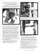
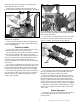
When properly adjusted, the powder bar will be
moved to the end of its travel by the cartridge case Fig. 9.
When you have determined that your adjustments
are correct, tighten the lock ring (#14067) and locking
collar (#13939). Fig. 10
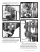
Failsafe Assembly
The purpose of the powder measure failsafe rod is to
return the powder bar to its closed position.
Remove the blue cap from the powder die (#20320)
and loosely clamp the powder measure in position.
To install the failsafe rod (#13960) remove the blue
wing nut (#13799) and rod spring (#14033) from the
rod, then insert the bottom end through the 3/8”
eyebolt (#13089) that’s mounted on the left rear of the
main frame.
Next, using your thumb and index finger of your left
hand, move the locklink down and align the hole with
the slot on the bellcrank. Then, insert the rod through
the two holes and insert the failsafe rod clip (#13929).
Install the spring (#14033) and wing nut (#13799) on
the rod and screw the wing nut up until you feel light
tension on the spring. Tighten the powder measure
clamp screws (#14037).
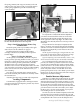
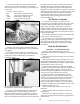
You will notice an adjusting bolt on the front of the
powder bar. Counterclockwise reduces the powder
charge, clockwise increases the charge. Fig. 11
Your machine comes with two powder bars. Fig. 12
One large (#20063) and one small (#20062). Rule of
thumb: Use the large bar whenever possible.
Index a sized and primed case under the measure
and operate the machine’s handle. Turning the powder
bar adjustment bolt clockwise increases the powder
charge – counterclockwise turns decreases the powder
charge. By trial and error, determine the correct weight
of your powder charge by using a powder scale. Fig. 11
When the correct powder charge had been set, cycle
several cases through the machine and check the load
with a scale.
Primer Magazine
Select the proper size primer pick-up tube and fill it
by placing the plastic tip over loose primers and
pressing down.
Fig. 10: Be sure to tighten the lock ring and locking collar when
adjustments are completed.
Collar
Fig. 12: Small powder bar (left), large powder bar (right).
Spacer
Fig. 11: Clockwise turns of the powder bar adjustment bolt will
increase the powder charge while counterclockwise turns will
decrease the powder charge.