
Manual

* Indicates a caliber specific part – see the caliber conversion
chart on page 19 for the caliber you are loading for.
6
If you get stuck on something that you don’t
understand, call (800) 223-4570 for technical assistance.
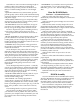
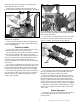
Step 1: Mounting the RL1050
Select a clear area on your reloading bench. Be certain
your bench is free from vibration and is strong enough to
support your RL1050’s mass and operating force. If
possible attach your bench to the wall using screws.
Remove the RL1050 main frame from the packaging
and place it on your selected area. The crank extension
(#12901) should be to your right. Bring the machine to
the forward edge of your bench – be sure to allow
clearance for operation of the handle. Mark the four
mounting holes using the machine as a template.
Remove the machine and drill four 1/4” holes through
the bench. Replace the machine and bolt securely. Fig. 1
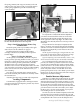
Install the handle (#12727) as indicated in the parts
schematic. Secure in place with the handle set screw
(#13432). You will note that there are three different
positions for mounting the operating handle. Choose
the one that feels best for you. The longer the handle is,
the less force is required but the stroke is longer.
The toolhead (#20420) is held down on the main
frame for shipping by the use of plastic ties. Remove the
ties while holding the handle.
Slowly move the handle up. This will move the
toolhead approximately three inches to its “up”
position. Note: If the handle is not moving freely,
carefully inspect for shipping damage.
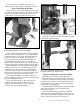
Install the six brass locator buttons (#20637*) around
the shellplate (#12600*). Fig. 2
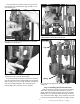
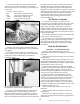
Step 2: Installing the Casefeed Assembly
Using the screw provided (#13377) install the
cartridge bin bracket (#13238) to the main frame. Fig. 3
Screw the casefeed post studs (#13271) to the main
frame (place the washer provided on the bottom post
only), tighten securely with an Allen wrench through
the cross hole provided. Fig. 3
Install the bullet bin bracket (#12144) to the casefeed
post (#20641) using the screw (#13685). See the
schematic on page 24.
The casefeed mounting post assembly (#20641) is
attached to the casefeed post studs (#13271) by the use
of two post bolts (#13205). Attach the power cable and
clamp as shown in the schematic on page 24.
Fig. 2: Locator button being inserted into its proper position.
Fig. 3: Place an Allen wrench into the cross hole and use it for
leverage to tighten the casefeed post studs.
Fig. 1: Be sure the machine is to the forward edge of the table or
bench when marking the four holes to be drilled.