
Manual

15
* Indicates a caliber specific part – see the caliber conversion
chart on page 19 for the caliber you are loading for.
Lower the platform and give the die an 1/8 turn
down, again raise the platform.
Lower the platform halfway and inspect the
cartridge. If the bell is still present, or the desired
amount of crimp has not been achieved, give the die a
1/8 turn down and try again. Continue making small
adjustments to your crimp die until the desired amount
of crimp has been achieved.
Once the adjustment is complete, place the case back
into Station 8 and raise the platform. Using a 1-1/8”
wrench to turn the lockring and a 7/8” wrench to hold
the die body, snug the lockring.
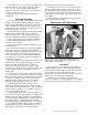
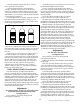
Note: See drawing (above). When adjusting the
crimp die it is important to know what to look for.
Check that the crimp: Looks OK, allows your firearm
to function consistently and the bullet feels tight in
the case.
The drawing of case #3 (above) is a depiction of a
case that has been over crimped by adjusting the
crimp die down (clockwise) too far. Note the defined
line below the mouth of the case and the bulge below
the line. This is not a proper crimp. This line is the
direct result of the cartridge being over crimped. A
line like this will only appear if the crimp die is
adjusted down too far. Warning: Over crimping
.45ACP, .38 Super, 9mm, etc., can actually cause the
bullet to be loose in the case.
Older Model RL1050 Users Section
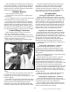
The casefeed spring (#13526) when adjusted
correctly, will keep the cases from becoming lodged
between the casefeed plate and the casefeed port. When
adjusting, position the spring as close as possible to the
casefeed plate in a location favoring the left side of
center in relation to the port opening. Allow one case
diameter (in perspective to the caliber) for clearance
between the spring and the leading edge of the exit port.
Note that the spring becomes the wall the case will hit it
before falling down the funnel.
Adjustments
for calibers 9mm, .38 Spl, .45 ACP and for hot
loads that have been fired many times
Configuration 1
Place a military case (sized, decapped and
unswaged) into Station 3.
Screw the backup rod (#12749*) down two turns into
the toolhead (#20420). Pull the handle.
Using a wrench turn the backup rod (#12749*)
down until it hits the inside bottom of the case. Note:
Do not force the expander as this will damage the case
and the shellplate. Now secure the lock ring (#20006*).
Raise the handle.
Screw the eyebolt (#13245) all the way into the
swager. Grease the clevis pin (#13522) heavily.
Put the swager into position. Push the clevis pin
through the connecting rod and eyebolt and secure with
the hitch pin (#13840). Replace the swage cover (#13064).
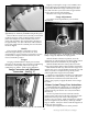
With the military case still in Station 3, pull the
operating handle down with your left hand. Now turn
the swager upward with your right hand until it meets
resistance. Fig. 17 With your left hand raise the
operating handle about 10”. With your right hand turn
the swager up a quarter turn. Cycle the handle down.
Raise the handle just enough to remove the case and
inspect the primer pocket to see the amount of swaging
being done. The swager should leave a radiused
entrance on the primer pocket. Turn the swager in,
using one quarter turn increments until you achieve the
proper swage. Secure the jam nut (#13682). Note: Do not
over swage. This condition will cause damage to the
shellplate (#12600*). When your swager is properly
adjusted you will feel resistance during the final 1/2” to
1” of the downward stroke of the handle.
Adjustments
for .223 and 7.62x39 Russian
Configuration 2
Place a military case (sized, decapped and
unswaged) into Station 3.
Remove the backup rod (#12749*) from the backup
die (#12184).
With the operating handle in the down position,
screw the backup die into Station 3 until the die
comes into contact with the shellplate. Now back the
die out one full turn and secure it in place with the
lock ring (#14067).
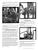
Leave the handle in the down position. With a
wrench screw the backup rod into the backup die. Turn
the backup rod down until it touches the inside bottom
of the case. Fig. 18 Note: Do not force the expander as
this will damage the case and the shellplate. Now secure
the lock ring (#20006*). Raise the handle.
Screw the eyebolt (#13245) all the way into the
swager. Grease the clevis pin (#13522) heavily.
Put the swager into position. Push the clevis pin
through the connecting rod and eyebolt and secure with
the hitch pin (#13840). Replace the swage cover (#13064).
With the military case still in Station 3, pull the
operating handle down with your left hand. Now turn
the swager upward with your right hand until it meets
resistance. Fig. 17 With your left hand raise the
operating handle about 10”. With your right hand turn
123