
Owner's manual


FI-521 Indicator Operation & Service Manual
────────────────────────────────────────────────────────
37
26.3.11 AVOUT Connect on Analog Voltage Output Sub-Board:
CONNECTED PINS FUNCTION
1 Analog Voltage Output +
2 Analog Voltage Output – (Internal Power GND)
Note:
The current draw from 1-2 connector should be less than 2.5mA, that means the resistor added
between 1-2 connector should more than 1K
M
!
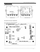
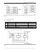
26.3.12 XIN (Remote Input) Connector:
26.3.12.1 Pin Definition
PIN # DEFINITION IN/OUT/POWE
R
ELECTRICAL LEVEL
1 Internal Power output + Power output 5 - 8Vdc (≤0.1A)
2 Input1+ input 5-24Vdc
3 Input1- input 0Vdc
4 Input2+ input 5-24Vdc
5 Input2- input 0Vdc
6 Input3+ input 5-24Vdc
7 Input3- input 0Vdc
8 Input4+ input 5-24Vdc
9 Input4- input 0Vdc
10 Internal Power output - Power GND 0 Vdc
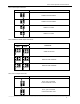
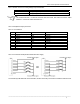
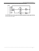
26.3.12.2 Connection Example When External Power Supply:
The remote keys RK1-RK4 also can be transistor, and the remote keys connection is isolated to internal circuit.