
Owner's manual


FI-521 Indicator Operation & Service Manual
────────────────────────────────────────────────────────
35
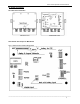
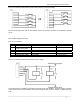
If a pigtail (an around 30cm cable with a 7-pin female connector) is used for loadcell interface,the cable
pinouts are:
A: Signal -
B: Excitation +
C: Signal +
D: Excitation -
E: Sense -
F: Sense +
G: Ground
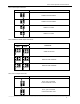
26.3.4 RS232 Connector:
PIN # DEFINITION IN/OUT/POWER ELECTRICAL LEVEL
1 COM1 Receive Input -12 to +12Vdc
2 COM1 Transmit Output -12 to +12Vdc
3 GND Power ground 0Vdc
4 GND Power ground 0Vdc
5 COM2 Receive Input -12 to +12Vdc
6 COM2 Transmit Output -12 to +12Vdc
26.3.5 RS485 Connector:
PIN # DEFINITION IN/OUT/POWER ELECTRICAL LEVEL
1 RS485 signal A Input/output 0Vdc
2 RS485 signal B Input/output 0-5Vdc
3 GND Power ground 0-5Vdc
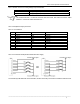
26.3.6 CAL Jumper set:
CONNECTED PINS FUNCTION
1-2 Calibration Enabled
2-3 Calibration Disabled
26.3.7 JP4 Jumper set:
CONNECTED PINS FUNCTION
1-2 RS485 terminal 120ohm resistor on board is disabled
2-3 RS485 terminal 120ohm resistor on board is enabled