
Owner's manual


FI-521 Indicator Operation & Service Manual
────────────────────────────────────────────────────────
34
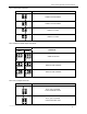
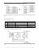
26.2.2 With Analog Voltage Output Board:
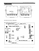
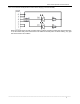
26.3 Definition of Sockets and Jumpers: (make sure the no.1 pin position, refer to 22.2)
26.3.1 ADP---adapter power input connector
PIN # DEFINITION IN/OUT/POWER ELECTRICAL LEVEL
1 Adapter input voltage + Power input 12Vdc(10.5-15Vdc,≥0.5A)
2 Adapter input voltage – (GND) Power ground 0Vdc
3 Shell Earth
26.3.2 BAT---Battery power input connector
PIN # DEFINITION IN/OUT/POWER ELECTRICAL LEVEL
1 Battery input voltage + Power input 5.6-7.2Vdc (6V lead acid
battery)
2 Battery input voltage – (GND) Power ground 0Vdc
26.3.3 LOADCELL Connector:
PIN # DEFINITION IN/OUT/POWER ELECTRICAL LEVEL
1 Excitation + Power output 5±0.3 Vdc (≤0.12A)
2 Sense + Power input 5±0.3 Vdc
3 Excitation- Power ground ≤0.5 Vdc
4 Sense - Power input 0Vdc
5 Signal + Signal Input 2.5±0.3 Vdc
6 Signal - Signal Input 2.5±0.3 Vdc
7 Shield - -