FI-521 Indicator Operation & Service Manual V1.
FI-521 Indicator Operation & Service Manual ──────────────────────────────────────────────────────── 2
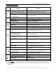
FI-521 Indicator Operation & Service Manual CONTENT 1. General information and warnings........................................................ 4 2. Specification ............................................................................................ 7 3. Faceplate .................................................................................................. 9 4. Summary of Key function ..................................................................... 10 5. Operation Menu Structure ...........
FI-521 Indicator Operation & Service Manual 1. General information and warnings 1.1 About this manual This manual is divided into chapters1,2.3.... Subsections are labeled as shown by the 1.1 and 1.1.1 headings. The manual name appear at the top of the pages and page numbers appear at the bottom of the pages. 1.1.1 Text conventions Key names are shown in bold and reflect the case of the key being described. This applies to hard keys and onscreen or soft keys. 1.1.
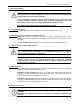
FI-521 Indicator Operation & Service Manual 1.3 Electrical installation ELECTRICAL WARNING: The power cable must be connected to an earth-grounded electrical outlet. The electrical supply must have a circuit breaker with an appropriate rating to protect from over-current conditions.
FI-521 Indicator Operation & Service Manual Always turn off the machine and isolate from the power supply before starting any routine maintenance to avoid the possibility of electric shock. Make sure that it is placed securely on a flat and level surface. 1.5 Cleaning the machine 1.6 Training Do not attempt to operate or complete any procedure on a machine unless you have received the appropriate training or read the instruction books.
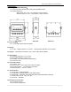
FI-521 Indicator Operation & Service Manual 2. Specification 2.1 Housing and Outline Dimension: 1.2.1 IP65 wash-down stainless steel housing with adjustable bracket 1.2.2 Outline Dimension: With bracket: 10.3" x 8.5" x 3.8" (262mm x 215mm x 96mm) Without bracket: 8.9" x 6.3" x 3.8" (225mm x 160mm x 96mm) Front View Side View 2.2 Power Supply: 2.2.1 12 Vdc / min.500mA output AC adapter Back View 2.3 Display: 2.3.1 FI-521: 7-digits,7-segment, 0.7’’(17mm) ultra brightness LEDs with 14 annunciators. 2.
FI-521 Indicator Operation & Service Manual 2.8.3 Peak Capture Rate: 80 Hz 2.8.4 Input range: -15mV to +15mV 2.8.5 Output code: 1mV input between S+ and S- of load cell connector will output about 100,000 raw Counts. 2.8.6 With Hardware low pass filter and 2 programmable digital low pass filters 2.9 Capacity and Division: Programmable 2.9.1 Max display range: -999,999 to 999,999 2.9.2 Max number range of all units = 100-100,000 2.9.3 Recommended Display Sensitivity: >0.5uV/ display division 2.
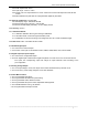
FI-521 Indicator Operation & Service Manual 3. Faceplate 3.1 Meaning of symbol on faceplate: 3.1.1 FORCE--------Illuminates when indicator is in force display mode. 3.1.2 PEAK----------Illuminates when indicator is in peak display mode. When it’s flashing, the displayed number is live force, when it’s steady, the number is peak force. 3.1.3 lbf,kgf,N------Illuminates the active unit of measure . 3.1.4 ----------Data Send: Illuminates when the indicator is transmitting data. 3.1.
FI-521 Indicator Operation & Service Manual 4.
FI-521 Indicator Operation & Service Manual 5. Operation Menu Structure 5.1 Main menu: CONFIG (Cell) USER (Cell) CAL (Cell) IN.OUT (Cell) MISC (Cell) TEST NOTE: (1) Each LOAD CELL has its own CONFIG, CAL, IN.OUT parameters, so, before you enter this main menu select, which load cell will be configured with the CELL key! (2) The parameters of USER, MISC, and TEST are the same for all load cells (3) When “Lo.VoL” or “Lo.BAT” is displayed (the voltage to PCB is low), CONFIG, USER, CAL, IN.
FI-521 Indicator Operation & Service Manual 5.2.16 Press CELL key. Display shows PRIM.D 5.2.17 Press ZERO key once. Display shows 1 5.2.18 Press CELL key or PRINT key to change the digit a. Once you make a choice press ZERO key to accept 5.2.19 Press CELL key. Display shows PRIN. 5.2.20 Press ZERO key. Display shows LbF a. Press CELL key to toggle between kgF or LbF 5.2.21 Press ZERO key to accept 5.2.22 Press ON/OFF key twice 5.2.
FI-521 Indicator Operation & Service Manual SECOND.N 100-125,000 10,000 the division number under second unit ,the max is 1.25*(PRIM.N), NEWTON.N 100 – 125,000 10,000 the division number under the NEWTON unit ,the max is 1.25*(PRIM.N), UNITS 0-6 6 units that can use UNIT key to select: 0=kgf, 1=lbf, 2=N(Newton), 3= kgf,lbf, 4=kgf,N, 5=lbf,N, 6=kgf,lbf,N refer to section5.12 for some limitation MOTION 1-255 4 Check motion window: 1-255=±0.25d *(1-255) OVER.
FI-521 Indicator Operation & Service Manual FILTER FLT1.TH 0-255 40 Enter digital filter1 threshold: 0=no filter1; 1-254=filter1 be used only when vibration in ±0.5d*(1-254) ; 255= filter1 be always used FLT1.ST 1-64 8 Digital filter1 intensity: averaged FLT2.TH 0-255 20 Enter digital filter2 threshold: 0=no filter2; 1-254=filter2 be used only when vibration in ±0.5d*(1-254) ; 255= filter2 be always used FLT2.ST 0-255 160 Digital filter2 intensity: FUNC F.
FI-521 Indicator Operation & Service Manual 5.3 USER Submenu: To enter this parameter, press and hold the SELECT key for 3 seconds until display shows CONFIG. Press CELL key to USER. Press ZERO key to RESET and press CELL key to COM1. USER SubMenu1 RESET COM1 SubMenu2 NO YES BAUD.RT BYT.FMT Option Default NO 1200 2400 4800 9600 19200 38400 57600 8N1 7O1 reset user parameters to default setting 9600 8N1 7E1 OUT.MOD NONE CONT PRINT CMD PRT.CMD PRT.
FI-521 Indicator Operation & Service Manual OUT1 MAX.MIN DATE TIME AD.CODE YES NO YES NO YES NO YES NO IN. mV/V STATUS B.LINE COM2 BAUD.RT NO NO YES NO YES NO NONE, LINE1 –9 YES/NO=enable/disable output max peak and valley value, prompt is “Max.”/ “Min.” Yes/No=enable/disable output date. Prompt is “DATE” Yes/No=enable/disable output time. Prompt is “TIME” NO Yes/No=enable/disable output ADC's code.
FI-521 Indicator Operation & Service Manual OUT2 TITLE YES NO IND.ID YES NO CELL. No CELL.TYP DSP.POL YES NO YES NO YES NO Yes/No=enable/disable output prompt of every output line NO Yes/No=enable/disable output indicator's ID number, Prompt is “IND. ID” NO Yes/No=enable/disable output load cell’s ID number, Prompt is “CELL No.” NO Yes/No=enable/disable output load cell’s type, Prompt is “CELL TYPE” NO Yes/No=enable/disable output load cell’s measure type, Prompt is “DSP.
FI-521 Indicator Operation & Service Manual OTHER NLD.RNG CMD.SRC 1-255 10 1-255=the range of force is ±1-255d; when current force is less than this value, the load cell can be regarded as no load on it. It must be bigger than (CONFIG.MOTION). COM1 Source of the executed command selection: NONE=no command will be executed; COM1= command from COM1 will be executed; COM2= command from COM2 will be executed; COM1-2= command from COM1 or COM2 will be executed; NONE COM1 COM2 COM1-2 A.OFF.T 0-255 OFF.
FI-521 Indicator Operation & Service Manual 5.4 CAL Submenu: To enter this parameter, press and hold the SELECT key for 3 seconds until display shows CONFIG. Press CELL key (2x) to CAL. Press ZERO key to enter Cal Menu. CAL SUBMENU1 SUBMENU2 OPTION CAL.ON REMARK Seal switch is on CAL.OFF Seal switch is off ZERO Only do zero point calibration, then go to CAL.END to end. (Only needed when a zero shift has occurred.) LINE CAL.
FI-521 Indicator Operation & Service Manual 5.5 IN.OUT Submenu: IN.OUT SUBMENU1 INPUT SUBMENU2 DEFAULT REMARK IN1.SELE IN2.CELL IN3.UNIT IN4.ZEO Select function(yyy) of each remote input(x) X=1-4; yyyy=SELE(select)/ CELL(cell)/ PRNT(print)/ UNIT(unit)/ ZERO(zero)/ OFF/ NONE(none); normally, one remote input is low (0), that means one external switch is closed OUT1.00 OUT2.
FI-521 Indicator Operation & Service Manual DATE display date and set date; details refer to section11 TIME display time and set time; details refer to section10 VER display firmware version; details refer to section12 COM2.TY Display type of COM2; details refer to section13 ABUS.CNT View times of occurred abuse on selected cell; details refer to section14 ZERO.OFS ZERO OFFSET: Current zero - Calibration zero; details refer to section15 5.7 TEST Submenu: TEST SUBMENU1 REMARK DISP.
FI-521 Indicator Operation & Service Manual 6. Normal Force Measure mode 6.1 During key operation, please note to use the second function of a key, press the key down over 3 seconds; to input data or select menu, use to process. 6.2 Power on indicator: when indicator is off, short press ON/OFF key to turn on; Power off indicator: when indicator is on, long press ON/OFF key to turn off the indicator. 6.
FI-521 Indicator Operation & Service Manual Table1: use Kgf as primary unit: Calibration division value 0.0001kgf 0.001kgf 0.01kgf 0.1kgf 1kgf 10kgf 0.0002kgf 0.002kgf 0.02kgf 0.2kgf 2kgf 20kgf 0.0005kgf 0.005kgf 0.05kgf 0.5kgf 5kgf 50kgf Display division value in different weight unit that can be used Kgf 0.0001 0.001 0.01 0.1 1 10 0.0002 0.002 0.02 0.2 2 20 0.0005 0.005 0.05 0.5 5 50 Lbf 0.0002 0.002 0.02 0.2 2 20 0.0005 0.005 0.05 0.5 5 50 0.001 0.01 0.1 1 10 Not available Newton 0.001 0.01 0.
FI-521 Indicator Operation & Service Manual 7. Calibration 7.1 Select the load cell (1-3) for recalibration with the cell key. If the load cell has not been configured; you will have to access the CONFIG submenu and select the load cell parameters Access the calibration mode by pressing theSELECT key for 3 seconds or more, until you see Config displayed. 7.2 Press theCELL key to select the Cal menu 7.3 Press the ZERO key to enter the calibration menu. a.
FI-521 Indicator Operation & Service Manual a. If yes is selected, the calibration will be saved and exit to the force mode when the load is removed. b. If no is selected, it will go to the next step. 7.15 Press the ZERO key to confirm 7.16 The first default standard weight is displayed after Cal.P3being shown. The default standard weight is 100 % of full scale. Use the SELECT, PRINT, CELL, UNIT keys to input the value of the loaded weight.
FI-521 Indicator Operation & Service Manual 9.2 To go to this working mode, press down SETLECT until CONFIG is shown, using CELL, PRINT and ZERO key to go to MISC - Code item, press ZERO to enter this mode and display ADC output raw code. 9.3 In this mode, first press ZERO key can set current code as a reference zero, and then to display net code, press ZERO again to clear this reference and display gross code. 9.
FI-521 Indicator Operation & Service Manual press ZERO to display COM2’s type (485, 232, None) 13.2 Press SELECT key to return to last menu item, press ON/OFF key to prepare to exit this mode 14. View the Times of Load Cell was Abused 14.1 Press down SELECT until CONFIG is shown, using PRINT or CELL key to select MISC-ABUS.CNT item, press ZERO to show the times of selected load cell had been abused (CLx.yyy). x=1,2,3; yyy=000-999 14.
FI-521 Indicator Operation & Service Manual 20.1 Before test the receiving function of COM1 or COM2, a cable is need to connect a PC and this indicator, and a software that is similar with Super Terminal of Windows is also need to run on PC to send bytes to this indicator. Please note: testing uses USER-COM1/2-BAUD.RT setting baud rate and 8N1 byte format, Hex data. 20.2 Press down SELECT more than 3s to enter MAIN MENU mode, using PRINT or CELL key to select TEST-COM1.RD or TEST-COM2.
FI-521 Indicator Operation & Service Manual 23.4 When “SPF1/2” is shown, use ZERO to enter set set-point1/2 data mode. When “UNIT.kgf/lbf/n” is shown, use CELL, PRINT, or UNIT key to select unit of input force number. After this, use CELL, PRINT, UNIT key to input force number, and then use ZERO to confirm and save them. 23.5 In normal force measure mode, if SPF1 or SPF2 is set bigger than 0, the electronic level on output line will change according to the setting of OUTx.yz. 23.
FI-521 Indicator Operation & Service Manual Measure unit ----1-3bytes:“ lbf”,“ kgf”, “N”, left aligned Current status-- 4bytes 25.4.2 If the force is overcapacity, the indicator will return eight “^” characters (the field of polarity, decimal point, force data is filled by “^”). 25.4.3 If the force is under capacity, it will return eight “_” characters (the field of polarity, decimal point, and force data is filled by “_”). 25.4.
FI-521 Indicator Operation & Service Manual Response: ^^^^^^^^U1U2 U3 H1H2H3 H4---over capacity _ _ _ _ _ _ _ _ U1U2 U3 H1H2H3 H4---under capacity - - - - - - - - U1U2 U3 H1H2H3 H4---zero-point error Note: U1U2 U3 is 1or 3 bytes according to current unit: kgf, lbf, N W1W2W3W4W5W6 U1U2 U3 H1H2H3 H4 ---normal data Note: The decimal point position is determined by CONFIG-PRIM.D 25.6.1.
FI-521 Indicator Operation & Service Manual X 58 0d power off the indicator, simulate OFF key ? others 25.7 Communication when USER-COM1/2-LAYOUT is set to MULTIPLE: 25.7.
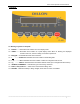
FI-521 Indicator Operation & Service Manual 26. Sockets and Jumpers 26.1 Back View of Indicator: With back cover without back cover 26.2 Sockets and Jumpers on Main Board 26.2.
FI-521 Indicator Operation & Service Manual 26.2.2 With Analog Voltage Output Board: 26.3 Definition of Sockets and Jumpers: (make sure the no.1 pin position, refer to 22.2) 26.3.1 ADP---adapter power input connector PIN # 1 2 3 DEFINITION Adapter input voltage + Adapter input voltage – (GND) Shell Earth IN/OUT/POWER Power input Power ground ELECTRICAL LEVEL 12Vdc(10.5-15Vdc,≥0.5A) 0Vdc ELECTRICAL LEVEL 5.6-7.2Vdc (6V lead acid battery) 0Vdc 26.3.
FI-521 Indicator Operation & Service Manual If a pigtail (an around 30cm cable with a 7-pin female connector) is used for loadcell interface,the cable pinouts are: A: B: C: D: E: F: G: Signal Excitation + Signal + Excitation Sense Sense + Ground 26.3.
FI-521 Indicator Operation & Service Manual 26.3.8 JP8 Jumper Connector: CONNECTED PINS FUNCTION COM2 is used as RS232 COM2 is used as RS485 COM2 is not used COM2 is not used 26.3.9 RXD2 and TXD2 Jumper Connector: CONNECTED TXD2 PINS RXD2 FUNCTION COM2 is not used COM2 is used as RS232 COM2 is used as RS485 26.3.
FI-521 Indicator Operation & Service Manual 26.3.11 AVOUT Connect on Analog Voltage Output Sub-Board: CONNECTED 1 2 PINS FUNCTION Analog Voltage Output + Analog Voltage Output – (Internal Power GND) Note: The current draw from 1-2 connector should be less than 2.5mA, that means the resistor added between 1-2 connector should more than 1KM ! 26.3.12 XIN (Remote Input) Connector: 26.3.12.
FI-521 Indicator Operation & Service Manual 26.3.12.3 Connection Example When Internal Power Supply (not recommended): The remote keys RK1-RK4 also can be transistor, and the remote keys connection is not isolated to internal circuit. 26.3.13 XOUT (Output) Connector: 26.3.13.
FI-521 Indicator Operation & Service Manual 25.3.13.3 Connection Example When Internal Power Supply (not recommended): When use internal power is used, the total current of output1 and output 2 draw (sink) must be less than 0.1A, that means heavy extra load should not be added on internal power! As above drawing, only light load can be used in this condition.
FI-521 Indicator Operation & Service Manual 27 Meaning of Some Symbols and Troubleshooting 27.1 Meaning of Symbols: 27.1.1 0﹉﹉﹉﹉ ------ Zero is over the setting range 27.1.2 0﹍﹍﹍﹍ ------ Zero point is below the setting range 27.1.3 Ad﹉﹉﹉ ------ Signal to ADC is over max. range) 27.1.4 Ad﹍﹍﹍ ------ Signal to ADC is below min. range 27.1.5 ﹉﹉﹉﹉ ------ Force is over upper limitation, or display data is over limitation 27.1.6 ﹍﹍﹍﹍ ------ Force is below lower limitation 27.1.7 EEP.
FI-521 Indicator Operation & Service Manual 27.2 Troubleshooting SYMPTOM Ad﹉﹉﹉ Ad﹍﹍﹍ 0﹉﹉﹉﹉ 0﹍﹍﹍﹍ PROBABLE Load cell wires CAUSE to indicator REMEDY are Make sure wires are ok and correctly incorrectly connected, or shorted, or connected. Replace load cell or ADC opened; or ADC, load cell are damaged chip, Service required. Weight reading exceeds Power On Zero limit. Perform zero calibration. Weight reading below Power On Zero calibration.
FI-521 Indicator Operation & Service Manual 28. Display Character Alpha LCD/LED Show Alpha A N B O C P D Q E R F S G T H U I V J W K X L Y M Z LCD/LED Show 29. Packing List No. CONTENT QTY 1 Indicator 1 2 User manual 1 3 Swivel bracket 1 4 6V2.
FI-521 Indicator Operation & Service Manual ──────────────────────────────────────────────────────── 43
FI-521 Indicator Operation & Service Manual Dillon USA 1000 Armstrong Dr. Fairmont MN 56031 Toll Free: 800-368-2031 Tel: 507-238-8796 Fax: 507-238-8258 Email: info@dillonforce.com www.dillonforce.com Model FI-521 Made in China Dillon UK Foundry Lane Smethwick West Midlands England B66 2LP Tel: +44 (0) 845 246 6717 Fax: +44 (0) 845 246 6718 Email: sales@dillono-force.co.uk www.dillon-force.co.