
User Manual


Replacing the Wave Bearings
Over time, the four plastic wave bearings (#13630)
may become worn. Follow these instructions to replace
the wave bearings:
1.) Remove any primers from the primer system by
removing the primer magazine tube (*#13879). Store live
primers safely!
2.) Remove the three screws (#13989) that attach the
primer system (*#20253 - see pg. 6) to the machine.
3.) Remove the primer system from the mac
hine.
4.) Disconnect the failsafe rod (#16814) by unclipping
it at the powder measure bellcrank.
5.) Remove the index bolt (#13461), located at the
back of the frame below the mounting surface. It may be
necessary to remove the machine from the bench to
access this bolt.
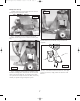
6.) Remove the four screws (#13896) which hold the
link arms (#13822) to the fr
ame.
7.) Support the shaft (#13437) with one hand and
remove the link arms.
8.) W
ithdr
a
w the shaft from the bottom of the fr
ame
(#13445).
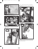
9.) Now the four wave bearings can be removed from
the inside of the frame and the replacements fitted.
10.) Reassembly is the rev
erse of the abo
v
e procedure.
Square Deal “B” Conversion Instructions
Changing calibers on your SDB is a simple procedure.
F
irst, y
ou must decide w
hether y
ou need to c
hange the
priming system that is now set up on your machine. Small
calibers use small pistol primers and large calibers use
large pistol primers. Skip step one if there are no primer
size changes.
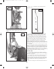
Step 1: Changing The Priming System
Remo
v
e Primer Early W
arning System. Remo
v
e three
screws (#13989 – refer to schematic) to remove the
primer system from the front of the mac
hine. Remove the
p
rimer slide return spring from pin (#13790) and remove
the primer slide assembly from the magazine system.
Replace the correct size primer slide in the same manner.
IMPORTANT Make sure the magazine is empty of all
primers by inverting the primer assembly.
Remove cap (#13957) and pull out the internal
magazine tube (#13673). Take the correct size magazine
tube and drop a primer, anvil side up, into the top of the
tube to make sure the primer drops freely through the
tube and orifice. Insert the magazine tube (#13673) into
the magazine shield with the keyed side of the orifice
pushed all the way down into the notch or key way in the
housing (#20900). Replace the cap (#13957). Do not over
tighten!
Now, insert a few primers, anvil side up, into the
magazine. Pull the handle, a full stroke, raise the handle
and a primer should appear at Station 2. If a primer fails
to appear, adjust the primer feed adjustment screw
(#13961a), located at the lower tip of the flat spring
(#13979) on the front of the housing (#20900) as follows:
If changing from a large primer to a small primer turn
the primer feed adjustment screw (#13961a) in 1/8 turn
increments clockwise. If changing from small to large,
turn in 1/8 turn increments counter
clockwise.
Cycle the handle again and a primer should appear. If
the primer cup is not centered under the shellplate or
snaps into place when the handle is raised it may be
necessary to adjust the primer slide travel by turning the
slide stop adjustment screw (#13961b) in 1/8 turn
increments. It is located between the primer slide and the
coiled spring (#13798) on the front on the housing. (see
pgs 3 & 4.)
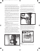
Step 2: Changing Shellplates
Lift out the ejector wire (#13433) and remove the
shellplate bolt (#13328). Carefully remove the shellplate
and be aware of a very small index ball (#14019) that sits
on a spring. Install the correct shellplate.
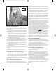
T
he short end of the ejector wire fits behind the
shellplate bolt (#13328). Note: The correct positioning of
the ejector wire is important or serious damage to the
sizing die could result. See F
ig. 6.
Step 3: Changing and Adjusting Dies
Use of Dillon’s Bench Wrench is suggested when
c
hanging or adjusting dies.
Remove screw (#13895) and remove the powder
measure. Remove screws (#13815) and (#14037) and
remove the toolhead assembly. Lift out the three die
inserts (#12864, #11628, #11734) from the frame. Note:
The toolhead you just removed is adjusted for those dies.
Store these parts for when you set up this caliber again.
Now, take the dies of the caliber that you are
converting to and insert them into the frame,
corresponding to the position reference number on eac
h
die. 1, 3 & 4. If you choose to use the toolhead you
removed, be certain that you back out the adjustment bolt
(#13908) at Station 4 and remo
v
e the seating stem at
Station 3.
12
Fig. 18
May 2007 Square Deal B Manual 5/17/07 2:23 PM Page 12