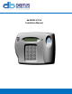
db NEXUS V3.0.
Table of Contents FCC Notice for db Nexus III ................................................................................................................................................................................... 3 Mounting the Head Unit ........................................................................................................................................................................................ 4 Mounting the Control Unit ...............................................
FCC Notice for db Nexus III This equipment has been tested and found to comply with the limits for a Class A digital device, pursuant to part 15 of the FCC Rules. These limits are designed to provide reasonable protection against harmful interference in a residential installation. This equipment generates, uses and can radiate radio frequency energy and, if not installed and used in accordance with the instructions, may cause harmful interference to radio communications.
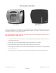
Mounting the Head Unit Front Section Back Section Locate a surface adjacent to the opening side of the door, making sure that a person can stand directly in front of the unit without obstruction. The unit should be positioned (where possible) on the wall so that the user’s forearm is approximately 90 degrees to the wall during operation. Prior to locating the back section of the head unit, double check that the cable passageway through the wall is clear from obstruction (e.g. pipes, cables, etc.
Mounting the Control Unit The control unit can be placed above a false ceiling or high up out of general reach, as no user interaction is necessary with this unit once installation is complete. Alternatively, all of the control units can be located centrally in a communication closet. The maximum distance between the head unit and the controller is 500 feet.
Connecting the Head Unit to the Control Unit • Once the control unit and the back plate of the head unit are securely mounted, run a 4-pair (8 conductor) cable between the head unit and control unit. A Belden 9504 or equivalent should be used. • The cable should leave the control unit via one of the push-out holes located on the bottom of the unit, running neatly along the wall and into the hole drilled through the rear of the head unit.
Connecting the Power Source to the Control Unit Please ensure that you have a power outlet near the control unit which will ONLY be used to supply power to the control unit. ONLY the transformer supplied by Digitus should be used to power the control unit (or an exact equivalent). • Strip approximately ¼” (6mm) of plastic sheath from each cable to the power supply and connect to the appropriate terminal blocks, checking that all wires are securely fastened.
Connecting an Electric Strike to the Control Unit • Fit an appropriate lock to the door. • The type of lock used determines how the control unit is wired. Fail Safe Locks and Magnetic Locks (12V) • A fail-safe or magnetic lock is permanently supplied with a 12V supply to keep the lock closed. • Connect the Ground Lead of the lock to a terminal labeled 0V. • Connect the Live Lead of the lock to the terminal labeled Door Solenoid.
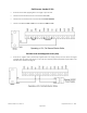
Fail Secure Locks (12V) • A fail secure lock needs supplying with a 12V supply to open the lock. • Connect the Ground Lead of the lock to the terminal labeled 0V. • Connect the Live Lead of the lock to the terminal labeled Door Solenoid. • Connect a link between Link and NC and a link between COM and 12V Fail Safe Locks and Magnetic Locks (24V) • A fail-safe or magnetic lock is permanently supplied with a 24V supply to keep the lock closed. The Digitus controller does not supply a 24V output.
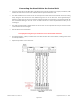
Fail Secure Locks (24V) • A fail secure lock needs supplying with a 24V supply to open the lock. The Digitus controller does not supply a 24V output. To use a 24V lock a separate power supply will be required. Wire a 24V Fail Safe lock as shown in the diagram: Models: db Nexus II, Nexus III Digitus Biometrics, Inc.
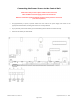
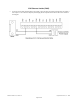
Request to Exit (RTE) Switch • The control unit has a built-in delay for the RTE switch. • Connect a push-switch as shown in the diagram below. The exit delay is set through the PC software on a networked unit or through the menus on the head unit for a standalone. Models: db Nexus II, Nexus III Digitus Biometrics, Inc.
Door Sensor • The door sensor contacts are used for the forced door and propped door features. • Connect the door sensor as shown below. • The door sensor circuit provides a feature to work with a special type of door sensor, that is tamper proof. This prevents an internal security breach, where someone with authorized access to an area could potentially shortout the contacts on the door sensor. If used with the anti-tamper door sensors, the jumper of SW SEL (JMP1) must be set as follows.
If the door sensor is not being used, the link must remain in place as shown below. Models: db Nexus II, Nexus III Digitus Biometrics, Inc.
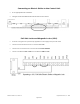
Fire Panel Integration • Units can be connected to a fire panel so that in the event of a fire, required doors can automatically unlock. • Once a door has been unlocked via the fire override inputs, the unit must be reset manually by pressing the reset button on the control unit. Doors will remain unlocked until the unit has been reset. • The diagram shows how to connect a control unit to a fire panel. The unit can be connect to either a normally open or normally closed set on contacts as shown below.
If the fire panel integration is not being used, the link must remain in place as shown below. Models: db Nexus II, Nexus III Digitus Biometrics, Inc.
Alarm Output • Certain conditions that occur on the unit will cause the Alarm Relay to operate. The Alarm Relay can be used to interface the control unit with a 3rd party system. When one of the following conditions happen, the 3rd party system will be alerted.
Wiegand Output (26-bit protocol) • The db Nexus controller offers a 26-bit Wiegand output, allowing seamless integration into 3rd-party Access Control System. • The diagram shows how to connect a control unit to a 3rd-party system. Models: db Nexus II, Nexus III Digitus Biometrics, Inc.
Network Connection • If the unit is networked, connect the RJ-45 plug as shown below. Models: db Nexus II, Nexus III Digitus Biometrics, Inc.
Powering Up the Unit • Plug the transformer in to the power outlet and ensure the supply is switched on. • The unit should now power up. If not, unplug the unit and check all wiring. • The buzzer on the control unit should sound for 1 second. Check the LCD display. If the display reads “LCD CONTRAST (0-9):[0] #=DONE the unit is OK. • If the unit does not get to this stage, or displays a different message, check that the cable between the head unit and control unit has been wired correctly.
Digitus Biometrics, Inc. 2 East Bryan Street, Ste 502 Savannah, GA 31401 USA Phone: 912-231-8175 Fax: 912.629.9478 www.digitus-biometrics.com support@digitus-biometrics.com Specifications subject to change without notice. Models: db Nexus II, Nexus III Digitus Biometrics, Inc.