
User's Manual
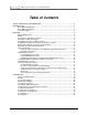
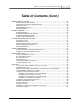
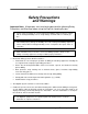
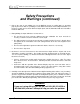
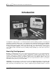
Table Of Contents
- Mark III Directional Drilling Locating System
- Table of Contents
- Table of Contents (Cont.)
- Table of Contents (Cont.)
- Safety Precautions and Warnings
- Safety Precautions and Warnings (Continued)
- Dear Customer:
- 3-3000-00b-F.pdf
- 3-3000-00c-F.pdf
- Receiver
- Display Window Icons
- On/Off
- Receiving the Transmitter’s Signals
- Clicking vs. Holding the Trigger
- Changing the Receiver’s Channel Setting
- Changing the Depth Measurement Units (English vs. Metric)
- Battery Status Display for Receiver and Transmitter
- Warning Tones for Transmitter Overheat
- Ultrasonic Function
- Calibrating the Receiver
- Using Depth Antenna Plumb Line to Mark Locate Points
- Finding Firmware Version
- 5.0 Series Firmware Functions
- Receiver
- 3-3000-00d-F.pdf
- 3-3000-00e-F.pdf
- 3-3000-00f-F.pdf
- 3-3000-00g-F.pdf
- 3-3000-00h-F.pdf
- 3-3000-00i-F.pdf
- 3-3000-00j-F.pdf
- Locating
- Locating Mode
- Locate Points (FNLP & RNLP) and Locate Line (PLL)
- Handling the Receiver
- Distance Between FNLP and RNLP Due to Depth, Pitch, and Topography
- Using Plus/Minus Indicators for Locating
- Locating the Transmitter from the Drill
- Locating the Transmitter from the Front
- Method for Confirming Position
- Locating on the Fly
- Off-Track Locating
- Splitting the Front and Rear Negative Locate Points
- Four-Turn Technique
- Calculating Depth Based on Distance Between FNLP & RNLP
- Running off Pitch or Calculating Depth from Pitch
- Transmitter’s Signal Shape
- Antenna Configuration
- Signal Reception
- Front and Rear Negative Locate Points
- Positive Locate Line Above Transmitter
- Locating
- 3-3000-00k-F.pdf
- 3-3000-00l-F.pdf
- 3-3000-00m-F.pdf
- 3-3000-00n-F.pdf
- 3-3000-00o-F.pdf
- 3-3000-00p-F.pdf
®
DIGITAL CONTROL INCORPORATED
Introduction
Remote Display
DataLog
Module
Receiver
Battery Charger
Transmitters
Cable
Transmitter
DigiTrak
®
Directional Drilling Locating System
The DigiTrak Locating System is used during horizontal directional drilling operations for locating and
tracking the transmitter within the tool. This manual provides detailed information about the DigiTrak
System and how to use it. The main system components are the Receiver, the Transmitter, the Remote
Display, and the Battery Charger, which are described below. The optional DataLog
®
System can be
used with the DigiTrak equipment to record and map your drilling data. These systems can be upgraded
for use with the Cable Transmitter System, providing locating capability up to 140 ft (42.7 m) from the
transmitter.
Basic DigiTrak Equipment
Receiver – The DigiTrak Receiver receives signals from the transmitter, processes the signal information,
and displays the transmitter’s status (roll, pitch, depth/distance, predicted depth, battery, and tem-
perature). It may also be equipped to send this information to the remote display at the drill. The most
current model of DigiTrak Receivers is the Mark III. Older versions are the Mark II or Mark I. Only on the
Mark III Receiver is the version identified; older versions are not specified on the receiver. If you need to
know what version you have, you can contact DCI.
Transmitter – Also referred to as a sonde, beacon, or probe, the DigiTrak Transmitter is placed in the drill
tool/housing to send information to the receiver. The receiver displays depth/distance, signal strength,
pitch, roll, battery, and temperature status. Power is supplied using C-cell alkaline batteries, except for
DigiTrak
®
Mark III Operator’s Manual 1