
User's Manual
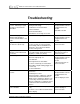
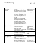
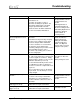
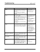


Table Of Contents
- Mark III Directional Drilling Locating System
- Table of Contents
- Table of Contents (Cont.)
- Table of Contents (Cont.)
- Safety Precautions and Warnings
- Safety Precautions and Warnings (Continued)
- Dear Customer:
- 3-3000-00b-F.pdf
- 3-3000-00c-F.pdf
- Receiver
- Display Window Icons
- On/Off
- Receiving the Transmitter’s Signals
- Clicking vs. Holding the Trigger
- Changing the Receiver’s Channel Setting
- Changing the Depth Measurement Units (English vs. Metric)
- Battery Status Display for Receiver and Transmitter
- Warning Tones for Transmitter Overheat
- Ultrasonic Function
- Calibrating the Receiver
- Using Depth Antenna Plumb Line to Mark Locate Points
- Finding Firmware Version
- 5.0 Series Firmware Functions
- Receiver
- 3-3000-00d-F.pdf
- 3-3000-00e-F.pdf
- 3-3000-00f-F.pdf
- 3-3000-00g-F.pdf
- 3-3000-00h-F.pdf
- 3-3000-00i-F.pdf
- 3-3000-00j-F.pdf
- Locating
- Locating Mode
- Locate Points (FNLP & RNLP) and Locate Line (PLL)
- Handling the Receiver
- Distance Between FNLP and RNLP Due to Depth, Pitch, and Topography
- Using Plus/Minus Indicators for Locating
- Locating the Transmitter from the Drill
- Locating the Transmitter from the Front
- Method for Confirming Position
- Locating on the Fly
- Off-Track Locating
- Splitting the Front and Rear Negative Locate Points
- Four-Turn Technique
- Calculating Depth Based on Distance Between FNLP & RNLP
- Running off Pitch or Calculating Depth from Pitch
- Transmitter’s Signal Shape
- Antenna Configuration
- Signal Reception
- Front and Rear Negative Locate Points
- Positive Locate Line Above Transmitter
- Locating
- 3-3000-00k-F.pdf
- 3-3000-00l-F.pdf
- 3-3000-00m-F.pdf
- 3-3000-00n-F.pdf
- 3-3000-00o-F.pdf
- 3-3000-00p-F.pdf

Troubleshooting
®
Problem/Concern Causes/Solutions Section to Consult
Minus sign (“–”) in bottom
window.
Receiver is set on ground for depth
reading, particularly at shallow depths, and
the ultrasonics are not reset. Reset the
ultrasonics.
Receiver has gone out of calibration.
Recalibrate using either 1-point or 2-point
calibration.
“Ultrasonic Function” in
Receiver Section
“Calibrating the Receiver”
in Receiver Section
Roll positions sticking or not
accurate.
Interference (squiggle in top left window
will not blink regularly).
If squiggle is blinking regularly, there may
be a transmitter or receiver malfunction. If
possible substitute a different receiver.
If you have a Mark III Receiver, conduct a
self-test for error code and failure
determination.
Transmitter has been overheated (temp
dot is black).
“Electrical Interference/
Background Noise Check”
in Signal Interference
Section
“Self-Test for Mark III
Receivers” in Operational
Tests Section
“Temperature Overheat” in
Transmitter Section
Not getting a solid depth
reading.
Interference.
The approximate depth may be calculated
using the pitch information along with the
distance between the FNLP and RNLP.
“Electrical Interference/
Background Noise Check”
in Signal Interference
Section
“Running Off Pitch or
Calculating Depth from
Pitch” in Locating Section
“Calculating Depth Based
on Distance Between
FNLP & RNLP” in
Locating Section
Bottom window depth/
distance flashes (with trigger
released).
Transmitter is being exposed to tempera-
tures in excess of 60ºC (140ºF). Verify
that temp dot is not black before further
use of transmitter.
Transmitter Section
Flashing squiggle (“~”) in
bottom window.
Transmitter has been exposed to tempera-
tures in excess of 60ºC (140ºF). Verify
that temp dot is not black before further
use of transmitter.
Transmitter Section
Solid squiggle (“~”) in bottom
window.
With 5.0 and later series firmware, the
receiver will display the transmitter’s
predicted depth at the FNLP in the bottom
window, along with a solidly illuminated
squiggle, when the trigger is held in. Pre-
5.0 series firmware will not do this.
“5.0 Series Firmware
Functions” in Receiver
Section
Locating Section
66 DigiTrak
®
Mark III Operator’s Manual