
User's Manual
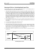


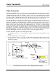

Table Of Contents
- Mark III Directional Drilling Locating System
- Table of Contents
- Table of Contents (Cont.)
- Table of Contents (Cont.)
- Safety Precautions and Warnings
- Safety Precautions and Warnings (Continued)
- Dear Customer:
- 3-3000-00b-F.pdf
- 3-3000-00c-F.pdf
- Receiver
- Display Window Icons
- On/Off
- Receiving the Transmitter’s Signals
- Clicking vs. Holding the Trigger
- Changing the Receiver’s Channel Setting
- Changing the Depth Measurement Units (English vs. Metric)
- Battery Status Display for Receiver and Transmitter
- Warning Tones for Transmitter Overheat
- Ultrasonic Function
- Calibrating the Receiver
- Using Depth Antenna Plumb Line to Mark Locate Points
- Finding Firmware Version
- 5.0 Series Firmware Functions
- Receiver
- 3-3000-00d-F.pdf
- 3-3000-00e-F.pdf
- 3-3000-00f-F.pdf
- 3-3000-00g-F.pdf
- 3-3000-00h-F.pdf
- 3-3000-00i-F.pdf
- 3-3000-00j-F.pdf
- Locating
- Locating Mode
- Locate Points (FNLP & RNLP) and Locate Line (PLL)
- Handling the Receiver
- Distance Between FNLP and RNLP Due to Depth, Pitch, and Topography
- Using Plus/Minus Indicators for Locating
- Locating the Transmitter from the Drill
- Locating the Transmitter from the Front
- Method for Confirming Position
- Locating on the Fly
- Off-Track Locating
- Splitting the Front and Rear Negative Locate Points
- Four-Turn Technique
- Calculating Depth Based on Distance Between FNLP & RNLP
- Running off Pitch or Calculating Depth from Pitch
- Transmitter’s Signal Shape
- Antenna Configuration
- Signal Reception
- Front and Rear Negative Locate Points
- Positive Locate Line Above Transmitter
- Locating
- 3-3000-00k-F.pdf
- 3-3000-00l-F.pdf
- 3-3000-00m-F.pdf
- 3-3000-00n-F.pdf
- 3-3000-00o-F.pdf
- 3-3000-00p-F.pdf

Cable Transmitter
®
Viewing the Cable System Battery Status
The percentage of required voltage will be displayed in the top left window of the remote display for 2
seconds when the transmitter’s temperature increases by 4°C, which will be displayed in the top right
window. To manually access the voltage status, turn the remote display off and on and observe the top
left window after the firmware version is displayed. The voltage status is displayed in percent remaining
(above the minimal necessary voltage) and is based on a 28V DC power source. Therefore, 28V will
display as 100%, 19V as 50%, 12V as 25%, 9V as 0%.
When a standard DCI battery pack is installed into the remote display, rather than the Cable Transmitter
Power Supply, it will automatically switch from the cable transmitter mode. Pitch, roll, temperature, and
battery status will again be received by telemetry from the DigiTrak Receiver.
Operation
The cable transmitter is located using the FNLP, RNLP, and PLL in the same manner as other DigiTrak
Transmitters, except the receiver will not display the transmitter’s pitch, roll, and battery or temperature
status—this information is displayed only on the remote display. Many cable bores do not allow walkover
locating; therefore, the depth of the transmitter is often calculated using the pitch information (see
“Running off Pitch or Calculating Depth from Pitch” in the Locating Section) or by using the real-time
DataLog System.
With the cable transmitter inside the housing/tool and grounded to the drill, complete a 1-point calibration
procedure. Ensure that there are no metal objects between the tool and the receiver during calibration.
Check depth readings against a measuring tape at varying distances from the cable transmitter.
Calibration can be done with the housing tool installed on the drill rig. The pitch angle does not affect
calibration.
Note that, because the cable transmitter emits twice the signal strength of a long-range transmitter (DX,
DXP, D4X, D4XP), the receiver will be saturated with signal at distances closer than 60 inches (152 cm).
Therefore, it may not be possible to obtain a depth reading at distances less than 60 inches (152 cm). To
determine the maximum depth range of the cable transmitter, move the receiver away from the
transmitter until the depth becomes very unsteady or reads “1999”. Although the depth of the tool can be
calculated from the pitch information, it will not be possible to locate the tool by walking over it at depths
greater than the maximum range. The ability to locate the FNLP and RNLP is also dependent on the
maximum depth range.
Ensure that the remote display and power supply are connected directly to the power source, not through
the drill’s DC power supply.
A multimeter should be available for power testing/troubleshooting. For detailed instructions on trouble-
shooting the Cable Transmitter System, please contact Customer Service at 425-251-0559 or 800-288-
3610.
3-3000-00k-F
62 DigiTrak
®
Mark III Operator’s Manual