
User's Manual
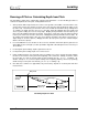


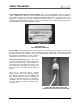

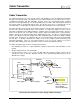

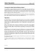
Table Of Contents
- Mark III Directional Drilling Locating System
- Table of Contents
- Table of Contents (Cont.)
- Table of Contents (Cont.)
- Safety Precautions and Warnings
- Safety Precautions and Warnings (Continued)
- Dear Customer:
- 3-3000-00b-F.pdf
- 3-3000-00c-F.pdf
- Receiver
- Display Window Icons
- On/Off
- Receiving the Transmitter’s Signals
- Clicking vs. Holding the Trigger
- Changing the Receiver’s Channel Setting
- Changing the Depth Measurement Units (English vs. Metric)
- Battery Status Display for Receiver and Transmitter
- Warning Tones for Transmitter Overheat
- Ultrasonic Function
- Calibrating the Receiver
- Using Depth Antenna Plumb Line to Mark Locate Points
- Finding Firmware Version
- 5.0 Series Firmware Functions
- Receiver
- 3-3000-00d-F.pdf
- 3-3000-00e-F.pdf
- 3-3000-00f-F.pdf
- 3-3000-00g-F.pdf
- 3-3000-00h-F.pdf
- 3-3000-00i-F.pdf
- 3-3000-00j-F.pdf
- Locating
- Locating Mode
- Locate Points (FNLP & RNLP) and Locate Line (PLL)
- Handling the Receiver
- Distance Between FNLP and RNLP Due to Depth, Pitch, and Topography
- Using Plus/Minus Indicators for Locating
- Locating the Transmitter from the Drill
- Locating the Transmitter from the Front
- Method for Confirming Position
- Locating on the Fly
- Off-Track Locating
- Splitting the Front and Rear Negative Locate Points
- Four-Turn Technique
- Calculating Depth Based on Distance Between FNLP & RNLP
- Running off Pitch or Calculating Depth from Pitch
- Transmitter’s Signal Shape
- Antenna Configuration
- Signal Reception
- Front and Rear Negative Locate Points
- Positive Locate Line Above Transmitter
- Locating
- 3-3000-00k-F.pdf
- 3-3000-00l-F.pdf
- 3-3000-00m-F.pdf
- 3-3000-00n-F.pdf
- 3-3000-00o-F.pdf
- 3-3000-00p-F.pdf
Cable Transmitter
®
Cable Transmitter
The cable transmitter has the same general features and capabilities as the other DigiTrak Transmitters
but with increased depth range. The dimensions of the cable transmitter are the same as those of the 2-
cell DigiTrak Transmitters (DT, DX, and DXP). However, there is also a power/signal cable extending
from the rear metal grounding cap. The metal grounding cap must make solid contact with the interior of
the housing, which is grounded through the drill. The function of the wire is to provide power to the
transmitter and to send the pitch, roll, voltage, and temperature information to the remote display.
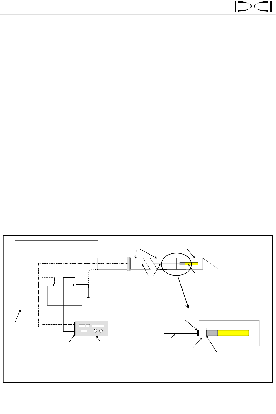
The cable transmitter is inserted into the transmitter housing, using the cable extraction/insertion tool, so
that the cable extends through the back of the housing. A compression fitting is used to seal the
transmitter compartment from drilling fluid/water. Optimal compression fitting characteristics include a
washer in the uphole side of the rubber stopper (inside compression fitting) and/or a tapered-interior-
diameter shaft to avoid stopper inverting due to drilling fluid pressure. The cable is routed through the
interior of the drill pipe; it exits the drill pipe at the drive chuck with another compression fitting or through
the mud swivel. As drill rods are added, the wires are connected using butt splices plus heat shrink with
hot melt glue. A slip-ring or mud-swivel assembly can be used to enable constant monitoring of the
transmitter information. These are not required; however, if one is not used, it will be necessary to
disconnect while drilling and reconnect the wires in order to view the transmitter information.
The Cable Transmitter System has the following characteristics:
¾ The calibration procedure is a 1-point calibration; 2-point is required if the cable transmitter is in the
ground.
¾ An input voltage between 12V and 28V DC.
¾ The typical power source is one or two 12V DC lead-acid automotive batteries, which may be
connected in series for 24V DC. With this 24V DC source, approximately 2000 ft (610 m) can be
drilled before recharge.
12-Volt
Battery
–
+
Drill Rig
Remote Display
Power Supply
Housing
Cable Transmitter
Drill Rods
Cable
Ground
Compression
Fitting
End Plug
Housing to Transmitter
Base is Negative
Contact for Grounding
Cable
White
Green
Black
Connecting Cable Transmitter to Power Supply and Remote Display
60 DigiTrak
®
Mark III Operator’s Manual