
User's Manual
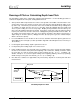


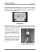

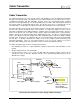

Table Of Contents
- Mark III Directional Drilling Locating System
- Table of Contents
- Table of Contents (Cont.)
- Table of Contents (Cont.)
- Safety Precautions and Warnings
- Safety Precautions and Warnings (Continued)
- Dear Customer:
- 3-3000-00b-F.pdf
- 3-3000-00c-F.pdf
- Receiver
- Display Window Icons
- On/Off
- Receiving the Transmitter’s Signals
- Clicking vs. Holding the Trigger
- Changing the Receiver’s Channel Setting
- Changing the Depth Measurement Units (English vs. Metric)
- Battery Status Display for Receiver and Transmitter
- Warning Tones for Transmitter Overheat
- Ultrasonic Function
- Calibrating the Receiver
- Using Depth Antenna Plumb Line to Mark Locate Points
- Finding Firmware Version
- 5.0 Series Firmware Functions
- Receiver
- 3-3000-00d-F.pdf
- 3-3000-00e-F.pdf
- 3-3000-00f-F.pdf
- 3-3000-00g-F.pdf
- 3-3000-00h-F.pdf
- 3-3000-00i-F.pdf
- 3-3000-00j-F.pdf
- Locating
- Locating Mode
- Locate Points (FNLP & RNLP) and Locate Line (PLL)
- Handling the Receiver
- Distance Between FNLP and RNLP Due to Depth, Pitch, and Topography
- Using Plus/Minus Indicators for Locating
- Locating the Transmitter from the Drill
- Locating the Transmitter from the Front
- Method for Confirming Position
- Locating on the Fly
- Off-Track Locating
- Splitting the Front and Rear Negative Locate Points
- Four-Turn Technique
- Calculating Depth Based on Distance Between FNLP & RNLP
- Running off Pitch or Calculating Depth from Pitch
- Transmitter’s Signal Shape
- Antenna Configuration
- Signal Reception
- Front and Rear Negative Locate Points
- Positive Locate Line Above Transmitter
- Locating
- 3-3000-00k-F.pdf
- 3-3000-00l-F.pdf
- 3-3000-00m-F.pdf
- 3-3000-00n-F.pdf
- 3-3000-00o-F.pdf
- 3-3000-00p-F.pdf
®
Cable Transmitter
Power Supply
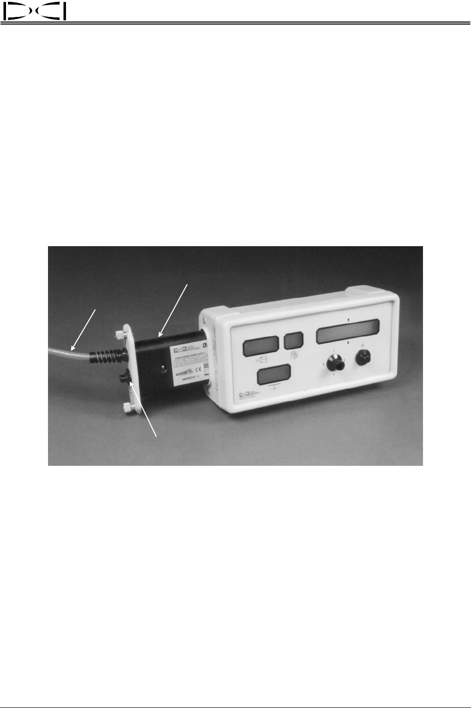
The Cable Transmitter Power Supply plugs into the remote display where a regular DCI battery pack is
normally placed. The power supply has three wires extending from it. The green and black wires should
be connected to a DC power source (green is positive, black is negative). The white wire is connected to
the cable transmitter (see sketch later in this section called “Connecting Cable Transmitter to Power
Supply and Remote Display”).
The power supply has the following features:
¾ There is an on/off button on the power supply that will disconnect power to the cable transmitter.
Power should be disconnected any time connections are made or broken. The red indicator light will
illuminate when power is supplied. To power up the Cable Transmitter System, it is necessary to turn
on both the remote display and the power supply.
Power Supply
Remote Display
On/Off Button
Cable (w/ Green,
Black, and
White Wires)
Cable Transmitter Power Supply Connected to Remote Display
¾ The power supply controls and limits the power to the cable transmitter. In the event of a short circuit,
power will be disconnected from the transmitter automatically. The power supply indicator light will go
out, and the transmitter will shut down. This condition can be corrected by eliminating the short
circuit. If the fault condition has been corrected, the power light will come back on automatically and
power will be restored to the transmitter.
¾ The power supply requires an input voltage of 12V to 28V DC.
¾ The power supply must be turned off at the end of the day to avoid overheating the cable transmitter.
NOTE: Do not use the drill’s power system as a source of power for the remote display and power sup-
ply. Run separate battery(ies) directly to the power supply, not through the auxiliary system on the drill.
The Cable Transmitter System can pick up electrical interference and noise introduced through the drill’s
power system.
DigiTrak
®
Mark III Operator’s Manual 59