
User's Manual
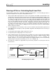


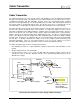

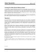
Table Of Contents
- Mark III Directional Drilling Locating System
- Table of Contents
- Table of Contents (Cont.)
- Table of Contents (Cont.)
- Safety Precautions and Warnings
- Safety Precautions and Warnings (Continued)
- Dear Customer:
- 3-3000-00b-F.pdf
- 3-3000-00c-F.pdf
- Receiver
- Display Window Icons
- On/Off
- Receiving the Transmitter’s Signals
- Clicking vs. Holding the Trigger
- Changing the Receiver’s Channel Setting
- Changing the Depth Measurement Units (English vs. Metric)
- Battery Status Display for Receiver and Transmitter
- Warning Tones for Transmitter Overheat
- Ultrasonic Function
- Calibrating the Receiver
- Using Depth Antenna Plumb Line to Mark Locate Points
- Finding Firmware Version
- 5.0 Series Firmware Functions
- Receiver
- 3-3000-00d-F.pdf
- 3-3000-00e-F.pdf
- 3-3000-00f-F.pdf
- 3-3000-00g-F.pdf
- 3-3000-00h-F.pdf
- 3-3000-00i-F.pdf
- 3-3000-00j-F.pdf
- Locating
- Locating Mode
- Locate Points (FNLP & RNLP) and Locate Line (PLL)
- Handling the Receiver
- Distance Between FNLP and RNLP Due to Depth, Pitch, and Topography
- Using Plus/Minus Indicators for Locating
- Locating the Transmitter from the Drill
- Locating the Transmitter from the Front
- Method for Confirming Position
- Locating on the Fly
- Off-Track Locating
- Splitting the Front and Rear Negative Locate Points
- Four-Turn Technique
- Calculating Depth Based on Distance Between FNLP & RNLP
- Running off Pitch or Calculating Depth from Pitch
- Transmitter’s Signal Shape
- Antenna Configuration
- Signal Reception
- Front and Rear Negative Locate Points
- Positive Locate Line Above Transmitter
- Locating
- 3-3000-00k-F.pdf
- 3-3000-00l-F.pdf
- 3-3000-00m-F.pdf
- 3-3000-00n-F.pdf
- 3-3000-00o-F.pdf
- 3-3000-00p-F.pdf
®
Locating
Field Strength:
100%
0%
Field Strength:
100%
0%
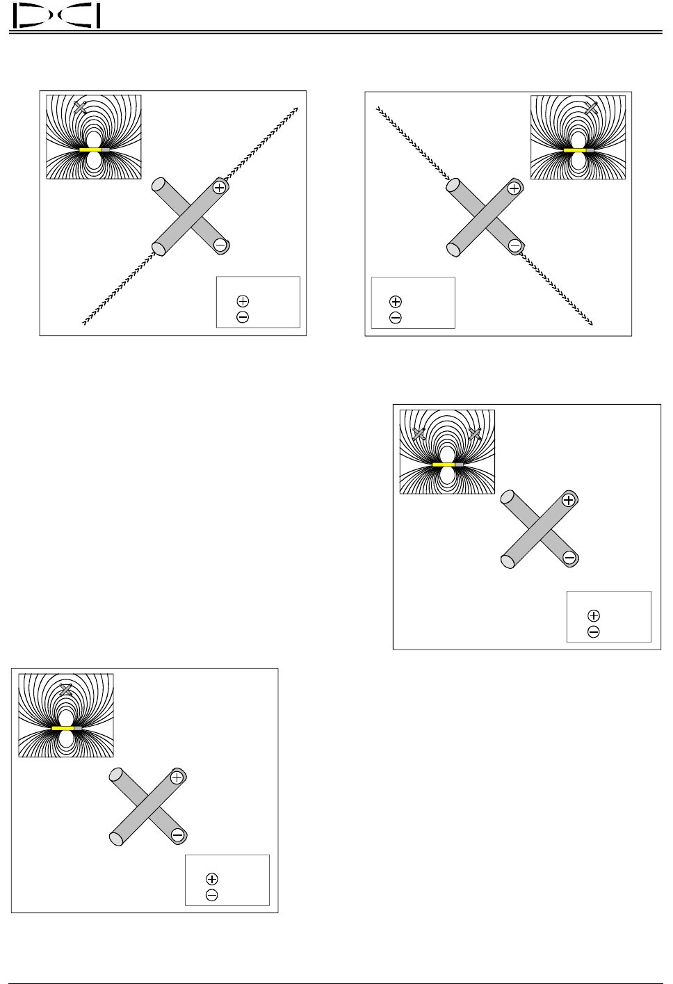
Parallel Field Lines and Antenna Perpendicular Field Lines and Antenna
Orientation of Field Lines with Respect to Antennas
>>>>>>>>>>>>>>>
>>>>>>>>>>>>>>>
Field Strength:
50%
50%
Vertical Field Lines at FNLP and RNLP
Front and Rear
Negative Locate Points
If the field line is vertical with respect to the antennas,
each antenna will read 50% of the signal (figure). This
occurs at two locations: one behind the transmitter,
known as the rear negative locate point (RNLP), and one
in front of the transmitter, known as the front negative
locate point (FNLP). Each of these locations is a specific
point that is independent of the transmitter’s signal
strength. Both the rear and front negative locate points
are important to accurately locating the transmitter, but
the FNLP is used more frequently. The FNLP is also
used to aid against oversteering.
>>>>>>>>>>>>>>>>>>>>>>>>>>>>>>>>>>>>
Field Strength:
50%
50%
Horizontal Field Lines at PLL
Positive Locate Line
Above Transmitter
When the field line is horizontal with respect to the
antennas, each antenna will read 50% of the field strength
at that point. This location is directly above the transmitter
and is referred to as the positive locate line (PLL). The
transmitter’s exact lateral location below the PLL can be
determined either by using the FNLP and RNLP or by
finding the peak signal. However, locating the trans-
mitter’s position below ground using the peak signal is not
encouraged due to its susceptibility to interference
potentials.
DigiTrak
®
Mark III Operator’s Manual 55