
User's Manual
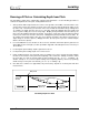


Table Of Contents
- Mark III Directional Drilling Locating System
- Table of Contents
- Table of Contents (Cont.)
- Table of Contents (Cont.)
- Safety Precautions and Warnings
- Safety Precautions and Warnings (Continued)
- Dear Customer:
- 3-3000-00b-F.pdf
- 3-3000-00c-F.pdf
- Receiver
- Display Window Icons
- On/Off
- Receiving the Transmitter’s Signals
- Clicking vs. Holding the Trigger
- Changing the Receiver’s Channel Setting
- Changing the Depth Measurement Units (English vs. Metric)
- Battery Status Display for Receiver and Transmitter
- Warning Tones for Transmitter Overheat
- Ultrasonic Function
- Calibrating the Receiver
- Using Depth Antenna Plumb Line to Mark Locate Points
- Finding Firmware Version
- 5.0 Series Firmware Functions
- Receiver
- 3-3000-00d-F.pdf
- 3-3000-00e-F.pdf
- 3-3000-00f-F.pdf
- 3-3000-00g-F.pdf
- 3-3000-00h-F.pdf
- 3-3000-00i-F.pdf
- 3-3000-00j-F.pdf
- Locating
- Locating Mode
- Locate Points (FNLP & RNLP) and Locate Line (PLL)
- Handling the Receiver
- Distance Between FNLP and RNLP Due to Depth, Pitch, and Topography
- Using Plus/Minus Indicators for Locating
- Locating the Transmitter from the Drill
- Locating the Transmitter from the Front
- Method for Confirming Position
- Locating on the Fly
- Off-Track Locating
- Splitting the Front and Rear Negative Locate Points
- Four-Turn Technique
- Calculating Depth Based on Distance Between FNLP & RNLP
- Running off Pitch or Calculating Depth from Pitch
- Transmitter’s Signal Shape
- Antenna Configuration
- Signal Reception
- Front and Rear Negative Locate Points
- Positive Locate Line Above Transmitter
- Locating
- 3-3000-00k-F.pdf
- 3-3000-00l-F.pdf
- 3-3000-00m-F.pdf
- 3-3000-00n-F.pdf
- 3-3000-00o-F.pdf
- 3-3000-00p-F.pdf

®
Locating
Running off Pitch or Calculating Depth from Pitch
The transmitter’s depth can be estimated by using the pitch information. Use the following procedure to
estimate the depth based on the pitch, starting with the first rod.
1. At the point the drill head penetrates the surface of the ground to the middle of the transmitter’s slots
(entry point), measure the amount of rod left on the rack (from the make-up/breakout clamps to the
top of the rod). This will tell you how much of the first rod with the transmitter will go underground.
To calculate the depth after the first rod, use the table below the DigiTrak Receiver handle and
choose a pitch reading closest to the entry angle. Multiply the depth number from the table by the
ratio of the rod length that went into the ground. For instance, using 10-ft (3-m) rods and measuring 8
ft (2.4 m) left on the rack, the ratio is 8/10 or 0.8. Multiply 0.8 by the depth number from the table. As
an example, if the launch angle is 28%, the closest pitch on the label is 30% which corresponds to a
depth change of 34 inches (86 cm). Multiply 34 inches (86 cm) by 0.8 to give the calculated depth,
which is 27.2 inches (69 cm).
2. For each additional rod, use the table on the receiver to determine how much depth is gained or lost
and multiply by the rod length (see table provided in Appendix called “Depth Increase in Inches per
10-foot Rod”).
3. For all negative pitch readings, depth is gained or increased.
4. For all positive pitch readings, depth is lost or decreased.
5. If pitch readings fluctuate over the length of the rod, it will be necessary to average the pitch readings
for that rod. For instance if the pitch at the beginning of the rod was 8%, halfway it read 6%, and at
the end it was 4%, then the average pitch for that rod will be 6% [(8 + 6 + 4) ÷ 3 readings = 6].
Another example is –2, 0, and 2 as pitch readings at the beginning, halfway, and end (respectively)
would average as a 0% pitch over that rod [(–2 + 0 + 2) ÷ 3 readings = 0].
6. Note that these estimates are approximate only and accuracy depends on accurate pitch and other
measurements.
Surface of
Ground
1 Drill Rod
Entry Point
Pitch Angles
Add to Depth
(Pitch "–")
Subtract
from Depth
(Pitch "+")
Calculating Depth from Pitch
DigiTrak
®
Mark III Operator’s Manual 53