
User's Manual
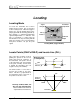
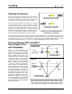

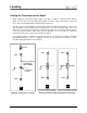
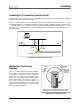


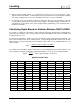
Table Of Contents
- Mark III Directional Drilling Locating System
- Table of Contents
- Table of Contents (Cont.)
- Table of Contents (Cont.)
- Safety Precautions and Warnings
- Safety Precautions and Warnings (Continued)
- Dear Customer:
- 3-3000-00b-F.pdf
- 3-3000-00c-F.pdf
- Receiver
- Display Window Icons
- On/Off
- Receiving the Transmitter’s Signals
- Clicking vs. Holding the Trigger
- Changing the Receiver’s Channel Setting
- Changing the Depth Measurement Units (English vs. Metric)
- Battery Status Display for Receiver and Transmitter
- Warning Tones for Transmitter Overheat
- Ultrasonic Function
- Calibrating the Receiver
- Using Depth Antenna Plumb Line to Mark Locate Points
- Finding Firmware Version
- 5.0 Series Firmware Functions
- Receiver
- 3-3000-00d-F.pdf
- 3-3000-00e-F.pdf
- 3-3000-00f-F.pdf
- 3-3000-00g-F.pdf
- 3-3000-00h-F.pdf
- 3-3000-00i-F.pdf
- 3-3000-00j-F.pdf
- Locating
- Locating Mode
- Locate Points (FNLP & RNLP) and Locate Line (PLL)
- Handling the Receiver
- Distance Between FNLP and RNLP Due to Depth, Pitch, and Topography
- Using Plus/Minus Indicators for Locating
- Locating the Transmitter from the Drill
- Locating the Transmitter from the Front
- Method for Confirming Position
- Locating on the Fly
- Off-Track Locating
- Splitting the Front and Rear Negative Locate Points
- Four-Turn Technique
- Calculating Depth Based on Distance Between FNLP & RNLP
- Running off Pitch or Calculating Depth from Pitch
- Transmitter’s Signal Shape
- Antenna Configuration
- Signal Reception
- Front and Rear Negative Locate Points
- Positive Locate Line Above Transmitter
- Locating
- 3-3000-00k-F.pdf
- 3-3000-00l-F.pdf
- 3-3000-00m-F.pdf
- 3-3000-00n-F.pdf
- 3-3000-00o-F.pdf
- 3-3000-00p-F.pdf

Locating
®
7. Repeat steps 2 through 6 until the “+/–” signs flip from one to the other over a very small area. This is
either the FNLP or the RNLP. To find the other locate point, walk in the assumed direction of drilling.
If the signal strength increases you are at the RNLP; if it decreases you are at the FNLP.
8. To confirm you are over the FNLP or RNLP (as opposed to being over the transmitter), rotate the
receiver (with the trigger held in) 360° at the FNLP or RNLP. The signal strength should remain con-
stant during the entire rotation. If the signal strength changes significantly, you are not directly above
the FNLP or the RNLP.
Calculating Depth Based on Distance Between FNLP & RNLP
It is possible to estimate the transmitter’s depth should the information displayed in the depth/distance
window become unreliable. This is only possible if the pitch and negative locate points are reliable and
the ground surface is level.
To estimate the transmitter’s depth, first measure the distance between the FNLP and the RNLP. The
pitch of the transmitter must also be reliably known. Using the Depth Estimation Table below, find the
divider that most closely corresponds to the transmitter’s pitch. Then use the following formula to esti-
mate the depth:
Divider
RNLPandFNLPbetweenDistance
Depth =
For example, if the transmitter’s pitch is 34% then the corresponding divider value (from the table) is 1.50.
In this example, the distance between the FNLP and the RNLP is 11.5 ft (3.5 m). The depth would be:
7.66
1.50
ft 11.5
Depth ==
ft or approximately 7.7 ft (2.35 m)
Depth Estimation Table
Pitch Divider Pitch Divider Pitch Divider Pitch Divider
0 1.41 26 1.47 52 1.62 78 1.84
2 1.41 28 1.48 54 1.63 80 1.85
4 1.42 30 1.48 56 1.64 82 1.87
6 1.42 32 1.49 58 1.66 84 1.89
8 1.42 34 1.50 60 1.68 86 1.91
10 1.42 36 1.51 62 1.69 88 1.93
12 1.43 38 1.52 64 1.71 90 1.96
14 1.43 40 1.54 66 1.73 92 1.98
16 1.43 42 1.55 68 1.74 94 2.00
18 1.44 44 1.56 70 1.76 96 2.02
20 1.45 46 1.57 72 1.78 98 2.04
22 1.45 48 1.59 74 1.80 100 2.06
24 1.46 50 1.60 76 1.82
52 DigiTrak
®
Mark III Operator’s Manual