
User's Manual
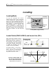
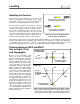
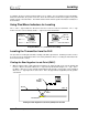
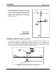

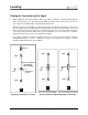
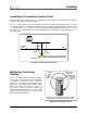


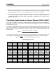
Table Of Contents
- Mark III Directional Drilling Locating System
- Table of Contents
- Table of Contents (Cont.)
- Table of Contents (Cont.)
- Safety Precautions and Warnings
- Safety Precautions and Warnings (Continued)
- Dear Customer:
- 3-3000-00b-F.pdf
- 3-3000-00c-F.pdf
- Receiver
- Display Window Icons
- On/Off
- Receiving the Transmitter’s Signals
- Clicking vs. Holding the Trigger
- Changing the Receiver’s Channel Setting
- Changing the Depth Measurement Units (English vs. Metric)
- Battery Status Display for Receiver and Transmitter
- Warning Tones for Transmitter Overheat
- Ultrasonic Function
- Calibrating the Receiver
- Using Depth Antenna Plumb Line to Mark Locate Points
- Finding Firmware Version
- 5.0 Series Firmware Functions
- Receiver
- 3-3000-00d-F.pdf
- 3-3000-00e-F.pdf
- 3-3000-00f-F.pdf
- 3-3000-00g-F.pdf
- 3-3000-00h-F.pdf
- 3-3000-00i-F.pdf
- 3-3000-00j-F.pdf
- Locating
- Locating Mode
- Locate Points (FNLP & RNLP) and Locate Line (PLL)
- Handling the Receiver
- Distance Between FNLP and RNLP Due to Depth, Pitch, and Topography
- Using Plus/Minus Indicators for Locating
- Locating the Transmitter from the Drill
- Locating the Transmitter from the Front
- Method for Confirming Position
- Locating on the Fly
- Off-Track Locating
- Splitting the Front and Rear Negative Locate Points
- Four-Turn Technique
- Calculating Depth Based on Distance Between FNLP & RNLP
- Running off Pitch or Calculating Depth from Pitch
- Transmitter’s Signal Shape
- Antenna Configuration
- Signal Reception
- Front and Rear Negative Locate Points
- Positive Locate Line Above Transmitter
- Locating
- 3-3000-00k-F.pdf
- 3-3000-00l-F.pdf
- 3-3000-00m-F.pdf
- 3-3000-00n-F.pdf
- 3-3000-00o-F.pdf
- 3-3000-00p-F.pdf

®
Locating
4. Step further to the side of the transmitter and again find the point where the “–” sign changes to a “+”
(Point 2).
5. Repeat this procedure to find the third location (Point 3).
When all three of these points are lined up, they confirm the location of the PLL, from which the heading
of the transmitter can be determined, because the PLL is at a 90° angle to the transmitter. As drilling
continues, the drill should be steered to maintain constant slant distances at either of Points 1, 2, or 3. If
the slant distance increases, the transmitter is moving away. If the slant distance decreases, the trans-
mitter is moving toward the side position.
Splitting the Front and Rear Negative Locate Points
At increased depths, a phenomenon occurs whereby the fine tuning of the FNLP and RNLP (when the
receiver is held perpendicular) results in a range or distance between the FNLP (or RNLP) which requires
you to “split” this range or distance for the true FNLP (or RNLP).
For instance, find the FNLP by walking out in front of the transmitter (your back is towards the drill). Now
turn perpendicular so your left shoulder faces the drill. With the trigger held in continue to walk towards
the left side of the drill string, note that the “+/–” signs will change back and forth from one to the other.
Continue walking until the minus sign “locks in” and mark this location. Turn 180° and walk towards the
right side of the drill string with the trigger held in. Continue walking until the minus sign finally “locks in”
and mark this location. The true FNLP will be found by “splitting” this distance between the two marked
locations you found. Use this same technique for fine tuning the RNLP.
Four-Turn Technique
The four-turn technique is another method for finding the FNLP or the RNLP. This may be used when a
new crew is sent to complete a bore that was started by another crew or to locate a “lost” transmitter. The
four-turn technique is so-named because the FNLP or RNLP is found by turning the receiver a maximum
of four 90° turns while following the “+/–” indicators.
To find the FNLP or the RNLP:
1. Be sure the transmitter is awake and the receiver has completed its start-up.
2. Hold in the trigger and rotate the receiver around the plumb line axis point (see the “Using Depth
Antenna Plumb Line to Mark Locate Points” in the Receiver Section) until you see a “+” sign in the top
left window.
3. Walk in the direction the receiver is facing when the “+” sign is found (keeping the trigger held in) until
the “+” sign changes to a “–” sign .
4. Turn the receiver 90° to the left.
5. You will see either a “+” sign or a “–” sign in the top left window (keeping the trigger held in). If you
see a “+” sign, walking forward. If you see a “–” sign, rotate the receiver 180° and you should see a
“+” sign. Walk in that direction.
6. When the “+” sign changes to a “–” sign, again turn the receiver 90°, looking for the “+” sign. If, after
turning the receiver 90° there is a “–” sign, turn 180° to obtain a “+” sign.
DigiTrak
®
Mark III Operator’s Manual 51