
User's Manual
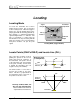
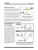
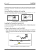
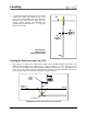

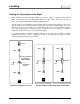
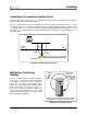


Table Of Contents
- Mark III Directional Drilling Locating System
- Table of Contents
- Table of Contents (Cont.)
- Table of Contents (Cont.)
- Safety Precautions and Warnings
- Safety Precautions and Warnings (Continued)
- Dear Customer:
- 3-3000-00b-F.pdf
- 3-3000-00c-F.pdf
- Receiver
- Display Window Icons
- On/Off
- Receiving the Transmitter’s Signals
- Clicking vs. Holding the Trigger
- Changing the Receiver’s Channel Setting
- Changing the Depth Measurement Units (English vs. Metric)
- Battery Status Display for Receiver and Transmitter
- Warning Tones for Transmitter Overheat
- Ultrasonic Function
- Calibrating the Receiver
- Using Depth Antenna Plumb Line to Mark Locate Points
- Finding Firmware Version
- 5.0 Series Firmware Functions
- Receiver
- 3-3000-00d-F.pdf
- 3-3000-00e-F.pdf
- 3-3000-00f-F.pdf
- 3-3000-00g-F.pdf
- 3-3000-00h-F.pdf
- 3-3000-00i-F.pdf
- 3-3000-00j-F.pdf
- Locating
- Locating Mode
- Locate Points (FNLP & RNLP) and Locate Line (PLL)
- Handling the Receiver
- Distance Between FNLP and RNLP Due to Depth, Pitch, and Topography
- Using Plus/Minus Indicators for Locating
- Locating the Transmitter from the Drill
- Locating the Transmitter from the Front
- Method for Confirming Position
- Locating on the Fly
- Off-Track Locating
- Splitting the Front and Rear Negative Locate Points
- Four-Turn Technique
- Calculating Depth Based on Distance Between FNLP & RNLP
- Running off Pitch or Calculating Depth from Pitch
- Transmitter’s Signal Shape
- Antenna Configuration
- Signal Reception
- Front and Rear Negative Locate Points
- Positive Locate Line Above Transmitter
- Locating
- 3-3000-00k-F.pdf
- 3-3000-00l-F.pdf
- 3-3000-00m-F.pdf
- 3-3000-00n-F.pdf
- 3-3000-00o-F.pdf
- 3-3000-00p-F.pdf
®
Locating
Finding the Front Negative Locate Point (FNLP)
4. At the PLL, con-
tinue
walking away
from the drill with
the trigger held in;
the signal strength
will decrease.
When the “+” sign
flips to a “–” sign,
this is the FNLP.
Again, move the
receiver forward
and backward a
little pinpointing
the location where
the “+/–” signs flip
from one to the
other.
FNLP
Surface of
Ground
Transmitter
Drill
Plus
Changes
to Minus
Finding the Front Negative Locate Point (FNLP) from the Drill
PLL
Drill
Plus
Changes
to Minus
RNLP
5. To find the actual location of the FNLP, turn toward
the left so that the receiver is perpendicular (90°) to
the drill string and move the receiver toward the left
side of the drill string and, again, move the receiver
forward and backward until pinpointing the location
where the “+/–” signs flip from one to the other.
Mark this spot.
6. When the trigger is held in at the FNLP (and only
the FNLP) the bottom window displays a prediction
of the transmitter’s depth as it would pass under the
FNLP, assuming no change in the pitch of the
transmitter. To distinguish the predicted depth from
the slant distance (trigger released), the bottom
window will flash the predicted depth with a solidly
illuminated squiggle (“~”). For receivers that have
pre-5.0 series firmware, the predicted depth feature
is not available. (see “5.0 Series Firmware
Functions” in the Receiver Section)
Fine Tuning
the FNLP
(Walking
Toward Left)
DigiTrak
®
Mark III Operator’s Manual 47