
User's Manual
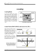
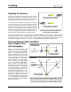
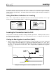
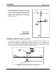

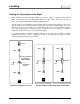
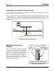


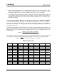
Table Of Contents
- Mark III Directional Drilling Locating System
- Table of Contents
- Table of Contents (Cont.)
- Table of Contents (Cont.)
- Safety Precautions and Warnings
- Safety Precautions and Warnings (Continued)
- Dear Customer:
- 3-3000-00b-F.pdf
- 3-3000-00c-F.pdf
- Receiver
- Display Window Icons
- On/Off
- Receiving the Transmitter’s Signals
- Clicking vs. Holding the Trigger
- Changing the Receiver’s Channel Setting
- Changing the Depth Measurement Units (English vs. Metric)
- Battery Status Display for Receiver and Transmitter
- Warning Tones for Transmitter Overheat
- Ultrasonic Function
- Calibrating the Receiver
- Using Depth Antenna Plumb Line to Mark Locate Points
- Finding Firmware Version
- 5.0 Series Firmware Functions
- Receiver
- 3-3000-00d-F.pdf
- 3-3000-00e-F.pdf
- 3-3000-00f-F.pdf
- 3-3000-00g-F.pdf
- 3-3000-00h-F.pdf
- 3-3000-00i-F.pdf
- 3-3000-00j-F.pdf
- Locating
- Locating Mode
- Locate Points (FNLP & RNLP) and Locate Line (PLL)
- Handling the Receiver
- Distance Between FNLP and RNLP Due to Depth, Pitch, and Topography
- Using Plus/Minus Indicators for Locating
- Locating the Transmitter from the Drill
- Locating the Transmitter from the Front
- Method for Confirming Position
- Locating on the Fly
- Off-Track Locating
- Splitting the Front and Rear Negative Locate Points
- Four-Turn Technique
- Calculating Depth Based on Distance Between FNLP & RNLP
- Running off Pitch or Calculating Depth from Pitch
- Transmitter’s Signal Shape
- Antenna Configuration
- Signal Reception
- Front and Rear Negative Locate Points
- Positive Locate Line Above Transmitter
- Locating
- 3-3000-00k-F.pdf
- 3-3000-00l-F.pdf
- 3-3000-00m-F.pdf
- 3-3000-00n-F.pdf
- 3-3000-00o-F.pdf
- 3-3000-00p-F.pdf
Locating
®
Receiver parallel to Transmitter
and facing in opposite direction
Receiver parallel to Transmitter
and facing in same direction
Receiver Can Face in Either Direction
with Respect to Transmitter
Handling the Receiver
For the most accurate locating, the receiver must be
held level and parallel to the transmitter. The receiver
can be held so that it faces in the same direction as the
transmitter or in the opposite direction (see sketch).
The front and rear negative locate points are denoted
as such because each is at a point where the sign
changes from positive to negative. It doesn’t matter if
the receiver and transmitter are facing in the same
direction or in opposite directions, the plus sign will
change to a minus sign at either of the locate points. In
fact, you can approach the FNLP or RNLP from any
direction and the sign will change from plus to minus.
The positive locate line (PLL) is not a point (like the FNLP and RNLP). As stated above, the PLL is a line
that runs perpendicular to the transmitter and is denoted as such because the negative sign will change
to a positive as the receiver crosses the PLL. The position of the transmitter along the PLL can be
determined by finding the FNLP. It can also be confirmed by finding the highest signal strength.
Distance Between FNLP and RNLP
Due to Depth, Pitch,
and Topography
Surface of
Ground
Bird's Eye View
(Looking Down)
Side View
Axis Line
FNLP
Transmitter (Negative
or Downward Pitch)
RNLP
RNLP FNLP
PLL
Transmitter (Negative
or Downward Pitch)
PLL
Drill
Drill
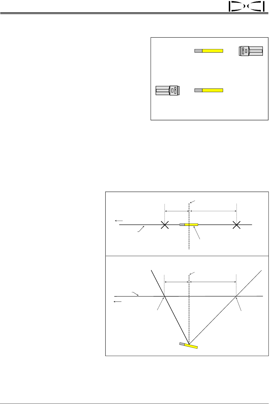
Effect of Pitch on Distance Between FNLP, RNLP, and PLL
Note how the RNLP and FNLP are at different distances from
the PLL when the Transmitter is at a negative pitch (compare
with sketch on previous page in which Transmitter is level).
Because of the transmitter’s field
shape, the deeper the transmitter,
the further apart the FNLP and RNLP
will be. The distance between the
FNLP and RNLP with respect to the
location of the PLL is also a function
of the transmitter’s pitch and the
topography. When the transmitter’s
pitch is negative, the FNLP will be
further from the PLL than the RNLP
(see sketch). When the transmitter’s
pitch is positive, the RNLP will be
further from the PLL than the FNLP.
If the ground surface or topography
slopes significantly, the locations of
the FNLP and RNLP will also be
affected with respect to the PLL even
though the transmitter itself is level.
Note that the distance between the
FNLP and the RNLP can be used to
calculate the depth of the transmitter
(see “Calculating the Depth Based on
Distance Between FNLP and RNLP”
later in this section).
44 DigiTrak
®
Mark III Operator’s Manual