
User's Manual
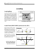
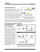
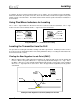
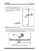

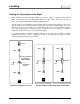
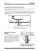


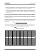
Table Of Contents
- Mark III Directional Drilling Locating System
- Table of Contents
- Table of Contents (Cont.)
- Table of Contents (Cont.)
- Safety Precautions and Warnings
- Safety Precautions and Warnings (Continued)
- Dear Customer:
- 3-3000-00b-F.pdf
- 3-3000-00c-F.pdf
- Receiver
- Display Window Icons
- On/Off
- Receiving the Transmitter’s Signals
- Clicking vs. Holding the Trigger
- Changing the Receiver’s Channel Setting
- Changing the Depth Measurement Units (English vs. Metric)
- Battery Status Display for Receiver and Transmitter
- Warning Tones for Transmitter Overheat
- Ultrasonic Function
- Calibrating the Receiver
- Using Depth Antenna Plumb Line to Mark Locate Points
- Finding Firmware Version
- 5.0 Series Firmware Functions
- Receiver
- 3-3000-00d-F.pdf
- 3-3000-00e-F.pdf
- 3-3000-00f-F.pdf
- 3-3000-00g-F.pdf
- 3-3000-00h-F.pdf
- 3-3000-00i-F.pdf
- 3-3000-00j-F.pdf
- Locating
- Locating Mode
- Locate Points (FNLP & RNLP) and Locate Line (PLL)
- Handling the Receiver
- Distance Between FNLP and RNLP Due to Depth, Pitch, and Topography
- Using Plus/Minus Indicators for Locating
- Locating the Transmitter from the Drill
- Locating the Transmitter from the Front
- Method for Confirming Position
- Locating on the Fly
- Off-Track Locating
- Splitting the Front and Rear Negative Locate Points
- Four-Turn Technique
- Calculating Depth Based on Distance Between FNLP & RNLP
- Running off Pitch or Calculating Depth from Pitch
- Transmitter’s Signal Shape
- Antenna Configuration
- Signal Reception
- Front and Rear Negative Locate Points
- Positive Locate Line Above Transmitter
- Locating
- 3-3000-00k-F.pdf
- 3-3000-00l-F.pdf
- 3-3000-00m-F.pdf
- 3-3000-00n-F.pdf
- 3-3000-00o-F.pdf
- 3-3000-00p-F.pdf
®
DIGITAL CONTROL INCORPORATED
Locating
Locating Mode
458
202
22
+
~
Plus (+)
Indicator
Signal
Strength
Predicted
Depth
Transmitter
Temperature
Locating Mode (Trigger Held In)
To locate the transmitter the receiver’s
trigger must be held in. This is referred to
as the “locating mode”. When the trigger is
held in, the top left window will stop dis-
playing pitch with the flashing pitch/roll up-
date squiggle (“~”) and will instead display
signal strength and the “+/–” indicator. The
plus (“+”) and minus (“–”) signs in the top
left window
are the key to locating and will
guide the operator to the tool (transmitter)
using three locations, not just the peak
signal.
Locate Points (FNLP
& RNLP) and Locate Line (PLL)
RNLP
FNLP
Transmitter
PLL
RNLP
FNLP
Surface of
Ground
Transmitter
Bird's Eye View
(Looking Down)
Side View
Axis Line
PLL
Drill
Drill
Two of the three locations used for
guiding the operator to the tool are
points that represent extensions of
the transmitter. One point is in front
of the transmitter (the front negative
locate point or FNLP), and the other
is behind the transmitter (the rear
negative locate point or RNLP).
The third location is a line that re-
presents the position of the trans-
mitter. This line is perpendicular to
the transmitter and is referred to as
the positive locate line or PLL.
Geometry of FNLP, RNLP, and
PLL from Top and Side Views
Note how RNLP and FNLP are
equal distances from the PLL.
DigiTrak
®
Mark III Operator’s Manual 43