
User's Manual
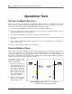
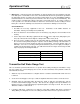


Table Of Contents
- Mark III Directional Drilling Locating System
- Table of Contents
- Table of Contents (Cont.)
- Table of Contents (Cont.)
- Safety Precautions and Warnings
- Safety Precautions and Warnings (Continued)
- Dear Customer:
- 3-3000-00b-F.pdf
- 3-3000-00c-F.pdf
- Receiver
- Display Window Icons
- On/Off
- Receiving the Transmitter’s Signals
- Clicking vs. Holding the Trigger
- Changing the Receiver’s Channel Setting
- Changing the Depth Measurement Units (English vs. Metric)
- Battery Status Display for Receiver and Transmitter
- Warning Tones for Transmitter Overheat
- Ultrasonic Function
- Calibrating the Receiver
- Using Depth Antenna Plumb Line to Mark Locate Points
- Finding Firmware Version
- 5.0 Series Firmware Functions
- Receiver
- 3-3000-00d-F.pdf
- 3-3000-00e-F.pdf
- 3-3000-00f-F.pdf
- 3-3000-00g-F.pdf
- 3-3000-00h-F.pdf
- 3-3000-00i-F.pdf
- 3-3000-00j-F.pdf
- Locating
- Locating Mode
- Locate Points (FNLP & RNLP) and Locate Line (PLL)
- Handling the Receiver
- Distance Between FNLP and RNLP Due to Depth, Pitch, and Topography
- Using Plus/Minus Indicators for Locating
- Locating the Transmitter from the Drill
- Locating the Transmitter from the Front
- Method for Confirming Position
- Locating on the Fly
- Off-Track Locating
- Splitting the Front and Rear Negative Locate Points
- Four-Turn Technique
- Calculating Depth Based on Distance Between FNLP & RNLP
- Running off Pitch or Calculating Depth from Pitch
- Transmitter’s Signal Shape
- Antenna Configuration
- Signal Reception
- Front and Rear Negative Locate Points
- Positive Locate Line Above Transmitter
- Locating
- 3-3000-00k-F.pdf
- 3-3000-00l-F.pdf
- 3-3000-00m-F.pdf
- 3-3000-00n-F.pdf
- 3-3000-00o-F.pdf
- 3-3000-00p-F.pdf

Operational Tests
®
3. Walk toward the axis line and watch for the plus (“+”) sign in the top left window to change to a minus
(“–”) sign. Note this location.
4. Continue past the axis line, then stop and turn the receiver 180° around so it is facing in the opposite
direction. Walk back toward the axis line from this opposite side and find
the location where the “+”
changes to a “–”.
5. These two
locations should be in the same place and lie on the axis line. If not, call DCI for
assistance.
Receiver Gain Test
Another test to confirm that the receiver is displaying the depth information correctly is to conduct a gain
test. This is a check of the receiver’s scaling system for depth and is similar to the old “walkie talkie” gain.
To complete the gain test, you will need an active transmitter, a tape measure, and the receiver.
1. Run the tape measure from the side of the transmitter (in or out of a drilling head) as if preparing for
1-point calibration (see “Calibrating the Receiver” in the Receiver Section). The tape measure should
extend out to the transmitter’s maximum range (see “Specifications” table in the Transmitter Section
for the maximum range ratings).
2. Place the receiver parallel to and 5 ft (1.5 m) from the transmitter and note the depth (do not hold in
the trigger).
3. Move the receiver 10 ft (3 m) away and note the depth.
4. Continue to check the depth as the receiver is moved away from the transmitter in 5-ft (1.5-m)
increments until maximum range is reached (“1999” will appear in the bottom window).
5. The final part of the gain test is to move the receiver back toward the transmitter at the same 5-ft
increments and verify that the depth information matches.
The depth readings at the 5-ft (1.5-m) increments should be the same whether the receiver is moved
toward or away from the transmitter. If they are significantly different, contact DCI for technical
assistance.
Transmitter Tests
¾ Temperature Indicator – Verify that the temperature indicator (temp dot) located at the front end of
the transmitter is white. Older transmitters have the temperature indicator located inside the battery
compartment, next to the battery terminal. If the temp dot has changed from white to black, then the
transmitter has been exposed to temperatures in excess of 220°F (104°C); for older models, the
maximum temperature is 180°F (82°C). Exposure to high temperatures may cause the transmitter’s
operation to be affected. A transmitter that has been overheated may appear to work fine; however, it
should be considered unreliable. The limited warranty on a transmitter is void if the transmitter has
been overheated or if the temperature indicator has been removed.
¾ Moisture – Verify that there is no moisture inside the battery compartment and that the springs inside
the battery compartment have not been permanently compressed.
38 DigiTrak
®
Mark III Operator’s Manual