
User's Manual
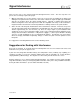
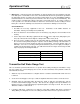


Table Of Contents
- Mark III Directional Drilling Locating System
- Table of Contents
- Table of Contents (Cont.)
- Table of Contents (Cont.)
- Safety Precautions and Warnings
- Safety Precautions and Warnings (Continued)
- Dear Customer:
- 3-3000-00b-F.pdf
- 3-3000-00c-F.pdf
- Receiver
- Display Window Icons
- On/Off
- Receiving the Transmitter’s Signals
- Clicking vs. Holding the Trigger
- Changing the Receiver’s Channel Setting
- Changing the Depth Measurement Units (English vs. Metric)
- Battery Status Display for Receiver and Transmitter
- Warning Tones for Transmitter Overheat
- Ultrasonic Function
- Calibrating the Receiver
- Using Depth Antenna Plumb Line to Mark Locate Points
- Finding Firmware Version
- 5.0 Series Firmware Functions
- Receiver
- 3-3000-00d-F.pdf
- 3-3000-00e-F.pdf
- 3-3000-00f-F.pdf
- 3-3000-00g-F.pdf
- 3-3000-00h-F.pdf
- 3-3000-00i-F.pdf
- 3-3000-00j-F.pdf
- Locating
- Locating Mode
- Locate Points (FNLP & RNLP) and Locate Line (PLL)
- Handling the Receiver
- Distance Between FNLP and RNLP Due to Depth, Pitch, and Topography
- Using Plus/Minus Indicators for Locating
- Locating the Transmitter from the Drill
- Locating the Transmitter from the Front
- Method for Confirming Position
- Locating on the Fly
- Off-Track Locating
- Splitting the Front and Rear Negative Locate Points
- Four-Turn Technique
- Calculating Depth Based on Distance Between FNLP & RNLP
- Running off Pitch or Calculating Depth from Pitch
- Transmitter’s Signal Shape
- Antenna Configuration
- Signal Reception
- Front and Rear Negative Locate Points
- Positive Locate Line Above Transmitter
- Locating
- 3-3000-00k-F.pdf
- 3-3000-00l-F.pdf
- 3-3000-00m-F.pdf
- 3-3000-00n-F.pdf
- 3-3000-00o-F.pdf
- 3-3000-00p-F.pdf
®
DIGITAL CONTROL INCORPORATED
Operational Tests
Self-Test for Mark III Receivers
Mark III Receivers have the capability of completing a diagnostic self-test to confirm proper operation.
This test must be conducted without a transmitter and in an interference-free environment. The self-test
procedure is conducted at start-up by clicking the trigger in a specific sequence.
1. Place a fully charged DigiTrak battery into the receiver and click the trigger once.
2. At the tone, quickly click the trigger 3 times (observe the number 3 in the bottom window). The test
takes approximately 15 seconds to complete.
3. If no problem is detected, the receiver will sound 3 tones, and turn itself off.
4. If the receiver detects a problem, it will display an error code in the top left window accompanied by 2
long tones.
5. An error code of “001” indicates high background noise; move to an interference-free area and con-
duct the self-test again.
For assistance with troubleshooting an error code call DCI.
Receiver Balance Check
If the receiver appears to be exhibiting a consistent left or right error, it is possible that the antennas in the
receiver are out of balance. It is also possible to find the transmitter further to the left or right if you use
only signal strength to locate the transmitter or if there is an interference source within proximity. The
transmitter’s location (depth and left/right position) should always be determined using the front and rear
negative locate points, not relying solely on peak signal.
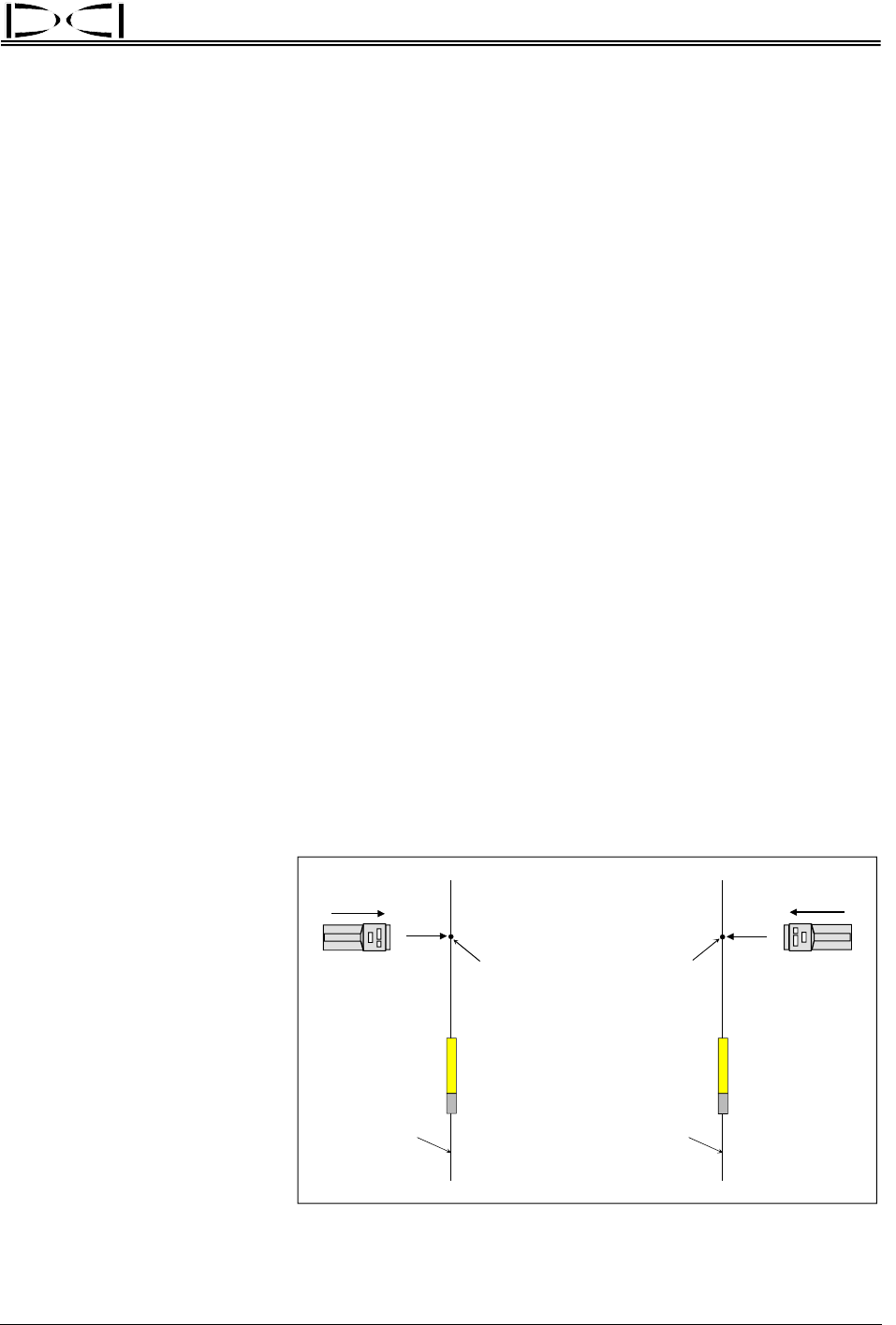
Axis
Line
Plus (+)
Changes to
Minus (–)
Axis
Line
Plus (+)
Changes to
Minus (–)
Receiver Balance Test – Make sure “+” changes to “–”
on same line coming from both directions.
To determine if the receiver’s
antennas are in balance, com-
plete the following test:
1. Place the transmitter on
the ground and step out in
front (or behind) about 10
to 12 ft (3 to 3.7 m) away
and a little to the left or
right side of the axis line
that extends from both
ends of the transmitter, as
shown in the drawing.
2. Hold the receiver perpen-
dicular to the transmitter
with the trigger held in.
DigiTrak
®
Mark III Operator’s Manual 37