
User's Manual
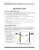


Table Of Contents
- Mark III Directional Drilling Locating System
- Table of Contents
- Table of Contents (Cont.)
- Table of Contents (Cont.)
- Safety Precautions and Warnings
- Safety Precautions and Warnings (Continued)
- Dear Customer:
- 3-3000-00b-F.pdf
- 3-3000-00c-F.pdf
- Receiver
- Display Window Icons
- On/Off
- Receiving the Transmitter’s Signals
- Clicking vs. Holding the Trigger
- Changing the Receiver’s Channel Setting
- Changing the Depth Measurement Units (English vs. Metric)
- Battery Status Display for Receiver and Transmitter
- Warning Tones for Transmitter Overheat
- Ultrasonic Function
- Calibrating the Receiver
- Using Depth Antenna Plumb Line to Mark Locate Points
- Finding Firmware Version
- 5.0 Series Firmware Functions
- Receiver
- 3-3000-00d-F.pdf
- 3-3000-00e-F.pdf
- 3-3000-00f-F.pdf
- 3-3000-00g-F.pdf
- 3-3000-00h-F.pdf
- 3-3000-00i-F.pdf
- 3-3000-00j-F.pdf
- Locating
- Locating Mode
- Locate Points (FNLP & RNLP) and Locate Line (PLL)
- Handling the Receiver
- Distance Between FNLP and RNLP Due to Depth, Pitch, and Topography
- Using Plus/Minus Indicators for Locating
- Locating the Transmitter from the Drill
- Locating the Transmitter from the Front
- Method for Confirming Position
- Locating on the Fly
- Off-Track Locating
- Splitting the Front and Rear Negative Locate Points
- Four-Turn Technique
- Calculating Depth Based on Distance Between FNLP & RNLP
- Running off Pitch or Calculating Depth from Pitch
- Transmitter’s Signal Shape
- Antenna Configuration
- Signal Reception
- Front and Rear Negative Locate Points
- Positive Locate Line Above Transmitter
- Locating
- 3-3000-00k-F.pdf
- 3-3000-00l-F.pdf
- 3-3000-00m-F.pdf
- 3-3000-00n-F.pdf
- 3-3000-00o-F.pdf
- 3-3000-00p-F.pdf

Signal Interference
®
There are two steps to the electrical interference/background noise check. The first step takes one
person; the second step requires two people.
1. With the transmitter off, test the amount of noise the receiver hears by holding in the trigger and
walking the borepath from the launch to the exit location. Watch the signal strength (top left window)
and note the locations where the signal strength changes. Typically, a reading greater than 150
indicates background noise that may interfere with the magnitude and shape of the transmitter’s
magnetic field lines and therefore alter the depth/distance readings and the locate points and line.
2. At the exit end of the borepath, install batteries in the transmitter to activate it. Then have one person
carry the transmitter along the borepath back to the drill while the other person walks in parallel at a
distance approximately one and one-half (1.5) times the target depth of your installation while
carrying the receiver. Do not hold in the trigger on the receiver; simply watch all the windows for any
changes in the transmitter’s information. Verify that the squiggle (“~”) in the top left window is flashing
every 2.5 seconds (indicating you are receiving pitch/roll updates). In particular, note any locations
where the display information inexplicably changes or where the pitch and roll updates become
infrequent.
See suggestions for dealing with interference in the following section.
Suggestions for Dealing with Interference
Every job site warrants an electrical interference/background noise check no matter how remote and
interference-free your job site appears to be.
If pitch and roll (along with transmitter battery and temperature status) suddenly stop updating, it is
sometimes possible to recover the signal by walking away from the transmitter in several directions,
staying within the published range. The objective is to move away from the interference source.
Another solution is to use a stronger-signal-strength transmitter. For example, if using a yellow standard-
range DT Transmitter, then try a red long-range DX Transmitter, and if you’re using a red DX Transmitter,
then try the Cable Transmitter. (See the Cable Transmitter Section.)
3-3000-00h-F
36 DigiTrak
®
Mark III Operator’s Manual